Week 8 Challenge
DATA GIVEN:-
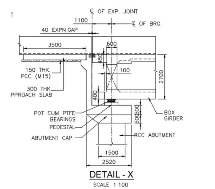
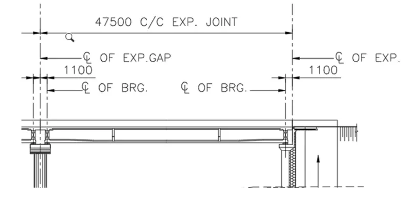
Basic Design Detail
| Sl. No | Span and Cross section | Quantity | Unit |
| 1 | C/c of expansin joint | 47.5 | m |
| 2 | C/c of bearing | 45.3 | m |
| 3 | Dist. Of bearing to expansion joint | 1.1 | m |
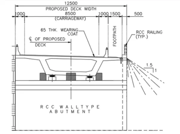
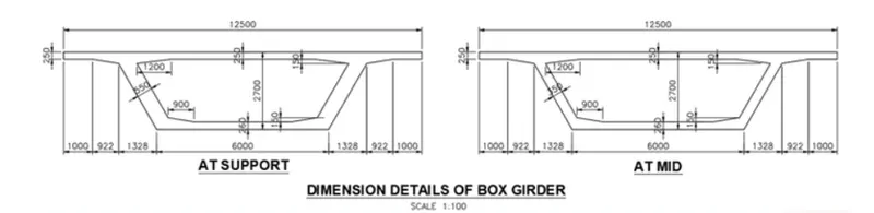
| 4 | Total width of the deck | 12.5 | m |
| 5 | Width of the carriageway | 8.5 | m |
| 6 | Footpath width (One Side) | 1.5 | m |
| 7 | Crashbarrier width | 1 | m |
| 8 | Median Gap | 1 | m |
Superstructure Details
| Sl.No | Items | Quantity | Unit |
| 1 | No of girders | 1 | |
| 2 | Depth of superstructure | 2.7 | m |
| 3 | Thickness of wearing coat | 0.065 | m |
| 4 | Bearing thickness | 0.065 | m |
| 5 | Pedestal thickness | 0.25 | m |
LEVEL:-
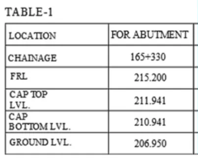
| 1 | Height of the Substructure | Assumption | 6 | m |
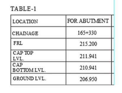
| 2 | Finished Road Level | FRL | 215.2 | m |
| 3 | Bearing Level | 212.256 | m | |
| 4 | Pier Cap Top level | 211.941 | m | |
| 5 | Pier Cap Bottom level | 210.941 | m | |
| 6 | Ground Level | GL | 206.95 | m |
| 7 | High Flood Level | HFL | 209.941 | m |
| 8 | Chainage | Ch. | 165+330 | m |
| 9 | Pile Cap top Level | 204.95 | m | |
| 10 | Depth of pile cap | Assume | 1.5 | m |
| 11 | Pile Cap Bottom level | 203.45 | m | |
| 12 | Clear Cover for Pile | 75 | mm |
Materials:-
| Sl. No | Particulars | Remarks | Values/Quantity | Units |
| 1 | Grade of concrete | fck M | 35 | Kn/m2 |
| 2 | Design strength of concrete | fcd | 15.63 | Kn/m2 |
| 3 | Grade of Steel | fyk Fe | 500 | Kn/m2 |
| 4 | Design strength of steel | fyd | 434.78 | Kn/m2 |
| 5 | Density of RCC | 2.5 | Kn/m3 | |
| 6 |
Density of W.C |
2.2 | Kn/m3 | |
| 7 | Coefficient of thermal expansion of concrete. | 1.2 | E-05/ c | |
| 8 | Shrinkage strain | 2 | E-04 | |
| 9 | Es | 200000 | Mpa | |
| 10 | Ec (M35) | 32000 | Mpa |
Water Current Data:-
| 1 | Max Mean velocity | 0.98 | m/s |
| 2 | Constant "K' for the pier in the transverse direction | 0.66 | |
| 3 | Constant "K' for the pier in the Longitudinal direction | 1.5 | |
| 4 | % of uplift consideration | 100 | % |
Soil Parameters:-
| Sl. No | Items | Value | Units |
| 1 | Angle of shear resistance | 30 | |
| 2 | Density of dry backfill | 2 | t/m3 |
| 3 | Density of submerged backfill | 1 | t/m4 |
| 4 | Net Soil Bearing Capacity | 25 | t/m5 |
| 5 | Gross SBC (LWL) | 33.42 | t/m6 |
| 6 | Gross SBC (HFL) | 27 | t/m7 |
| 7 | Live Load surcharge | 1.2 | m |
| 8 | Type of soil | median | soil |
| 9 | Coefficient of friction | 0.5 |
Factor of Safety for materials:-
| Material | Basic Combination | Seismic Combination |
| Concrete | 1.5 | 1.5 |
| Steel | 1.15 | 1.15 |
Loads on the Superstructure:-
Deadload on the Superstructure:-
| Total weight of superstructure | 300 | t |
| Reactions | 150 | t |
| Total reaction on abutment | 150 | t |
| Distance between BRG. & C/L of abutment shaft | 0 | m |
| Longitudinal movement | 0 | t-m |
| Transverse eccentricity of Dl from C/l of abutment | 0 | m |
| Transverse Movement | 0 | t-m |
SIDL (Excluding W.C)
| Crash barrier weight | 100 | t |
| Weight of the Railing | 0 | t |
| Foothpath / service weight | 0 | t |
| Total reaction on abutment | 50 | t |
SIDL (Excluding W.C)
| Load intensity due to wearing course | 0.22 | t |
| DL of wearing course | 150 | t |
| Total reaction on abutment | 75 | t |
Substructure
Abutment:-
Box part:-
| Length ( Longitudinal ) | 12.5 | m |
| Length ( Transverse ) | 2.52 | m |
| Height | 0.5 | m |
| Volume | 15.75 | m3 |
| Weight | 39.375 | t |
Trapezoidal Part:-
| Top Length | 12.5 | m |
| Bottom Length | 12.5 | m |
| Top width | 2.52 | m |
| Bottom width | 1.5 | m |
| Height | 0.5 | m |
| Volume | 12.5625 | m3 |
| Weight | 31.40625 | t |
| Total weight of pier cap | 70.78125 | t |
Abutment shaft:-
| Length ( Longitudinal ) | 12.5 | m |
| Length ( Transverse ) | 1.5 | m |
| Height | 6 | m |
| Volume | 112.5 | m3 |
| Weight | 281.25 | t |
LIVE LOADS:-
| 1 lane 70 R wheeled | |||
| Live Load reaction | |||
| Total live load | 100 | t | |
| No of lanes | 2 | nos | |
| % reduction in live load | 0 | % | reduction |
| impact factor - | 1.09 | As per IRC 6 | |
| Total load with imact | 109 | ||
| Ra | 99.3 | t | |
| Rb | 9.69 | t | |
| vertical reaction on the abutment | 99.3 | t | |
| Breaking force | 19.86 | t | 20 % of Ra |
| Total horizontal force at abutment | 9.93 | t | Fh/2 |
| Bearing Type | Elestometric Bearings | ||
| Transverse eccentricity | 3.155 | m | |
| Transverse movement | 313.2915 | t-m | |
| 1 lane Class A | |||
| Total live load | 55.4 | t | |
| No of lanes | 2 | nos | |
| % reduction in live load | 0 | % | reduction |
| impact factor - | 1.09 | As per IRC 6 | |
| Total load with imact | 60.386 | ||
| Ra | 36.67 | t | |
| Rb | 23.72 | t | |
| vertical reaction on the abutment | 36.67 | t | |
| Breaking force | 7.334 | t | 20 % of Ra |
| Total horizontal force at abutment | 3.667 | t | Fh/2 |
| Breaking Type | Elestrometric Bearings | ||
| Transverse eccentricity | 4.2 | m | |
| Transverse movement | 154.014 | t-m | |
Force summary at Foundation Bottom level:-
| Load Item | P | Load (Min) | ML | MT | HL | HT |
| t | t | t-m | t-m | t-m | t-m | |
| Dead Load | 150 | 0 | 0 | 0 | 0 | 0 |
| SIDL ( Exclding WC) | 60 | 0 | 0 | 0 | 0 | 0 |
| SIDL ( WC) | 75 | 0 | 0 | 0 | 0 | 0 |
| Class 70 R wheeled | 99.3 | 9.69 | 99.3 | 313.2915 | 9.93 | 0 |
| Class A vehicle | 36.67 | 23.72 | 36.67 | 154.014 | 3.667 | 0 |
Well Foundation:-
Well foundation is a type of deep foundation which is generally provided below the water level for bridges. Cassions or well have been in use for foundations of bridges and other structures since Roman and Mughal periods. The term 'cassion' is derived from the French word caisse which means box or chest. Hence cassion means a box like structure, round or rectangular, which is sunk from the surface of either land or water to some desired depth.
Open cassion is a box opened both at top and bottom. It is made up to either timber, concrete or steel. The open cassion is called well.
Well foundation is the most common type of deep foundation used for bridges in India.
A type of foundation where a part of the structure is hollow, which is generally built-in parts and sunk through ground or water to the prescribed depth by removing earth through a dredge hole.
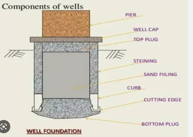
Components of well foundation.
- Well Cap
- Top plug
- Stening
- Bottom plug
- Well curb
- Cutting edge
- Filling inside ( Sand / Water )
Well Cap:-
A Well cap is a thick concrete mat that rests on the top of well stening. It is a part of the foundation and used to distribute loads of superstructure over the steining
Top Plug:-
It is a concrete layer of thickness around 500mm, as mentioned in design and drawing. Top plug provided over the filling and inside the well dredge hole.
Well Steining:
Steining is a wall or shall type of structure made up of RCC, and which helps to transfer the load to the curb. It serves as an enclosure for excavating the soil for the penetration of the foundation well
Bottom Plug:
After completion of sinking, the bottom of the foundation well is plugged with the help of concrete. The well curb confines the bottom plug, and functions like a raft against soil pressure from below
Well Curb:
Well Curb is a RCC ring beam-type component of well having a steel cutting edge below. Vertical cross-section of the well curb is wedge-shaped, which helps during the well sinking. The curb supports well steining, and the steining is kept slightly projected outer side to reduce the skin friction during well sinking
Cutting Edge:
It is the lowest part of the foundation well, and fabricated in the yard as per approved drawing. Cutting edge shall be fabricated in a number of segments depending upon circumference and ease of handling and transport. Cutting edge helps to cuts the soil during the sinking operation.
Back-filling:
The well is dewatered after setting of bottom plug concrete, and it is backfilled by sand or excavated approved material. Sometimes water can be used instead of sand/excavated material.
Field data required for Design of Wells:
- Design discharge from an authentic source
- Water surface slope on upstream and downstream
- Low water level and high flood level from an authentic source
- Silt factor from geotechnical investigation report
- Cross-section of the river
- Plain table survey of the river
- The deepest existing scour in the vicinity of the river.
- Strata chart i.e. bore log data.
- Availability of construction materials
Construction Sequence of Well Foundation:
Following steps in the sequence are to be executed:
- Setting out
- Cutting edge – fabrication, transportation, assembly, placing in final position
- Well curb construction – inner shuttering, reinforcement work, outer shuttering, concreting, curing, de-shuttering and grounding.
- Construction of steining and sinking
- Checking and monitoring tilt and shift
- Bottom Plugging, sand filling, top/intermediate plugging, if any, water filling, if any, and casting of well cap