Week 8 Challenge
AIM OF THE EXPERIMENT: To determine the centrifugal load acting on bridge and perform analysis in Staad.Pro.
THEORY:-
Centrifugual Force:- Centrifugal force is the apparent outward force on a mass when it is rotated. Think of a ball on the end of a string that is being twirled around, or the outward motion you feel when turning a curve in a car. In an inertial frame, there is no outward acceleration since the system is not rotating.
Mathematically:-C= (W x V2) / (127 x R)
Super elevation:- Super elevation is the banking of a roadway along a horizontal curve so motorists can safely and comfortably manoeuvre the curve at reasonable speeds. A steeper super elevation rate is required as speeds increase or horizontal curves become tighter.
Data Given:-
Span of bridge = 12.0 m
Width of carriage way = 7.0 m
Live load on bridge = Class 70R tracked vehicle.
Design Speed of vehicles = 75 km/hr
Radius of curvature = 3 m
Assumption:
Size of Pier = 1.5 m Diameter
Height of Pier = 10.0 m
Size of Girder beam = 2m x 1m
Size of Cross beam = 1m x 1m
Thickness of deck slab = 0.250 m
CALCULATIONS:-
According to IRC 6 code,
Live load of 70R tracked vehicle is 70KN
So, Live load (W) = 70 KN
Radius of curvature (R) = 3 m
Design speed (V) = 75 km/hr
Centrifugal Load (C) = (W x V2) / (127 x R) = (70 x 752) / (127 x 3) = 1033.5 KN
Procedures in Staad:-
STEP 1:-
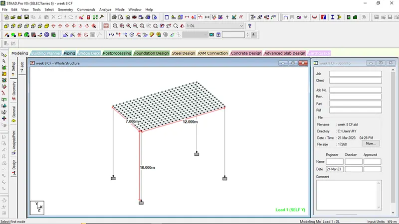
Model the bridge as per the given questions and mesh the top slab to get appropriate designed plate values.
STEP 2:-
Assigning of Property to the members and the top deck slab
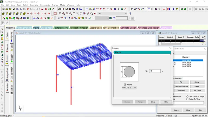
For Abutments, circular section 1.5m was taken.
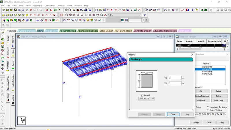
For longitudinal girder section, rectangular section of 1m x 2m was taken
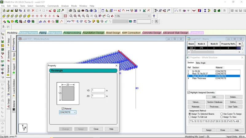
Rectangular section of 1m x 1m was taken for cross-girder elements.
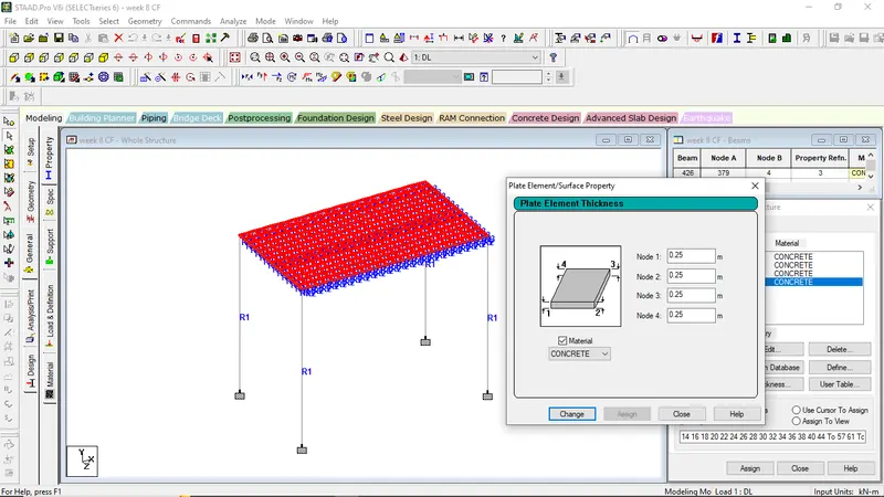
Deck Slab of uniform thickness of 0.250m was proposed for analysis
STEP 3:-
Providing fixed supports to the bridge
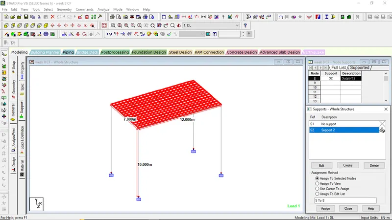
STEP 4:-
Assigning of DL and Centrifugal loads to the bridge:-
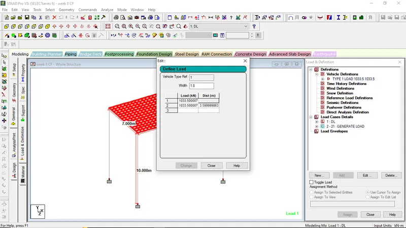
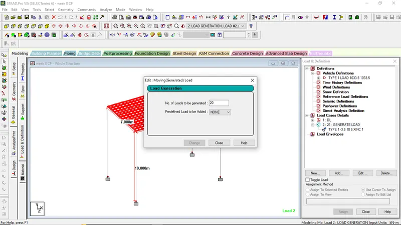
Assignation of Centrifugal loads to the bridge.
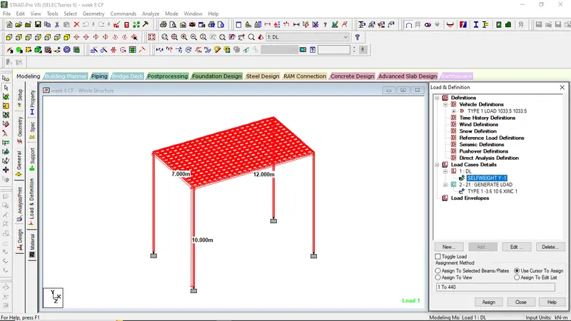
Assignation of DL to the structure
STEP 5:-
Analyzing the model structure:-
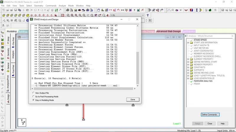
STEP 6:-
Go to the post processing mode and get the required values
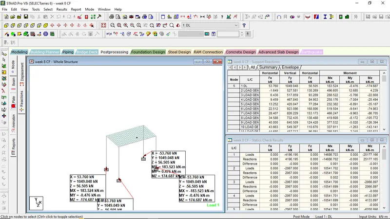
Maximum support reactions of the bridge for DL load case
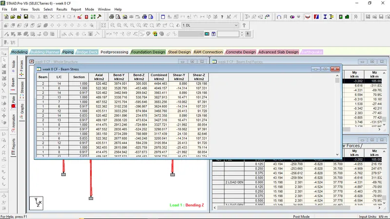
Maximum Beam Stress values
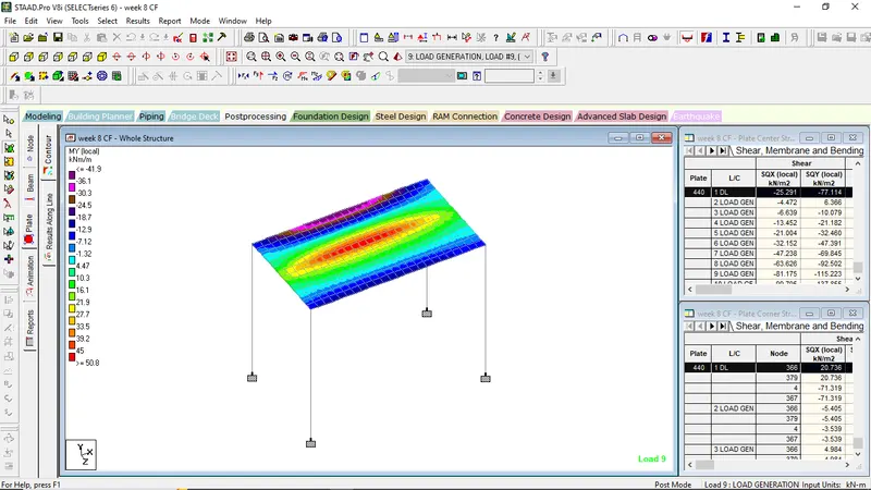
Plate contour showing MY local