Week 8 Challenge
DESIGN AND ANALYSIS OF BRIDGE WITH CENTRIFUGAL LOAD
AIM
To Design and analyse a bridge with Centrifugal load using STAAD Pro. Software.
INTRODUCTION
As per the given data and standard formulas the centrifugal load is being calculated manually.
As given in question Live load is 70 KN for 70 R tracked vehicle
so,Centrifugal force = WV^2/127 R
= 70 x 75^2/127 x 3
= 1034 KN
PROCEDURE
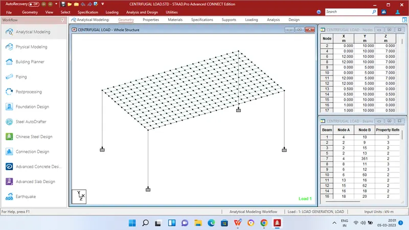
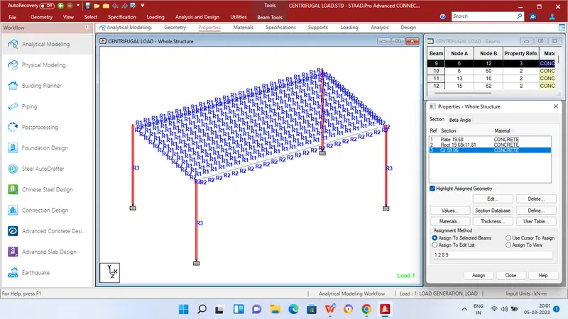
Step 1 - Create Nodes by entering the corresponding X/Y/Z values in the Node table for Creation of geometry for bridge structure with elements such as Piers,Beams,Deck slab etc.,
Step 2 - After creating the nodes connect those nodes with add beam option.
Step 3 - Then Click specification tab and click fixed support tab
Step 4 - After that in create support dialog box add fixed support for all the piers in the geometry using assign for selected nodes option.
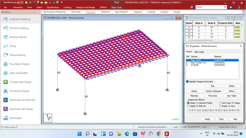
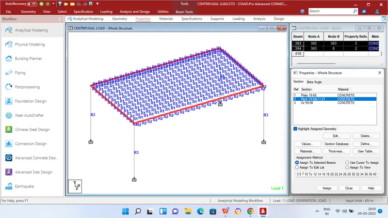
Step 5 - Then in Properties tab click Prismatic and add the Rectangle sections for beams - 300mm x 500mm,Circular dimension for piers - 1.5mm dia and 500mm thickness for plates.
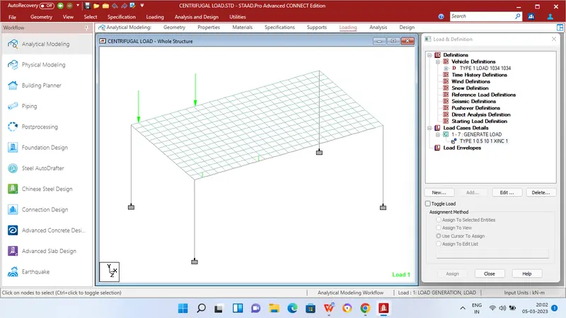
Step 6 - After adding the properties click Loading tab and define vehicle definition add 1034 KN as axle load and distance of 3.6m b/w axles.
Step 7 - Then apply Load generation for required no of loads click add and then find out the initial position of vehicle by using select node option and enter the corresponding x,y,z values also enter increment value.
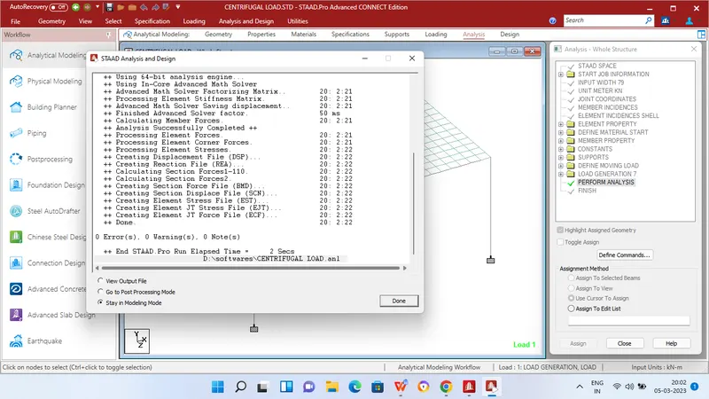
step 8 - Then in Analysis and design tab define commands for PERFORM ANALYSIS and click run analysis.
RESULTS
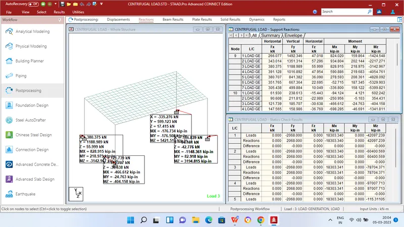
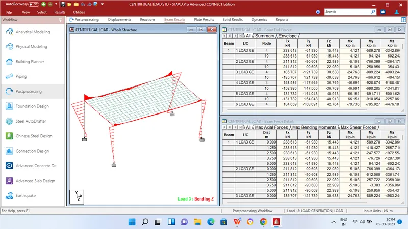
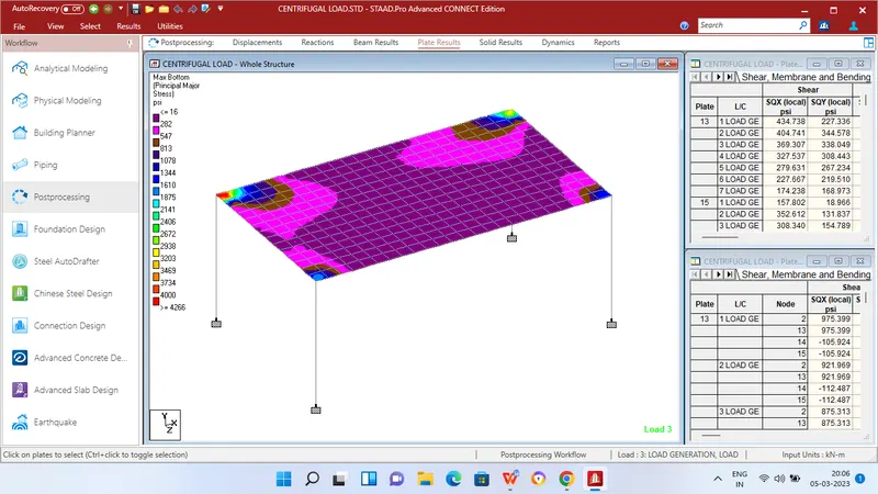
MAXIMUM BENDING MOMENT AT SUPPORT
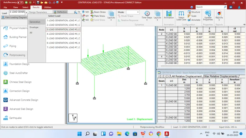
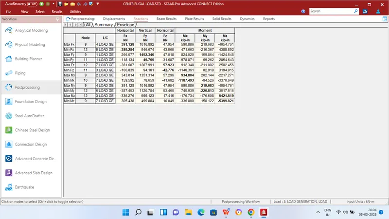
Mx = 934.804 KN/m at Node 9
My = 219.683 KN/m at Node 9
Mz = 5421.519 KN/m at Node 12
MAXIMUM SHEAR FORCE AT SUPPORT
Fx = 391.128 KN/m at Node 9
Fy = 1942.346 KN/m at Node 9
Fz = 57.923 KN/m at Node 12
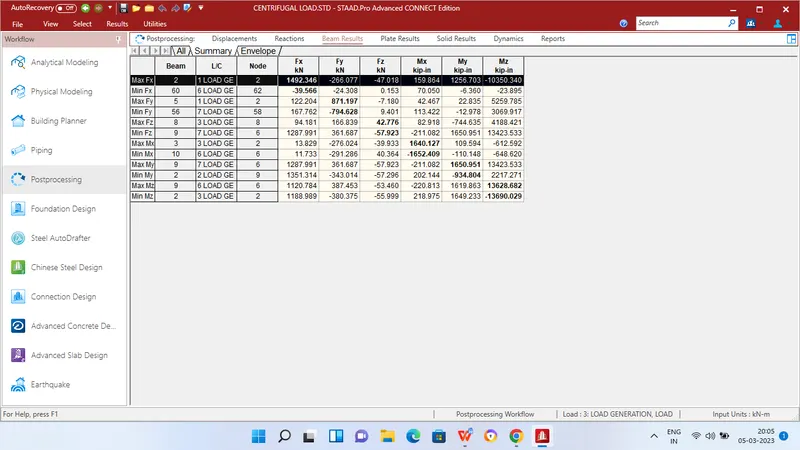
MAXIMUM BENDING MOMENT AT BEAMS
Mx = 1642.127 KN/m at Beam 3
My = 1650.951 KN/m at Beam 9
Mz = 13628.682 KN/m at Beam 9
MAXIMUM SHEAR FORCE AT BEAMS
Fx = 1492.346 KN/m at Beam 2
Fy = 871.197 KN/m at Beam 5
Fz = 42.776 KN/m at Beam 8
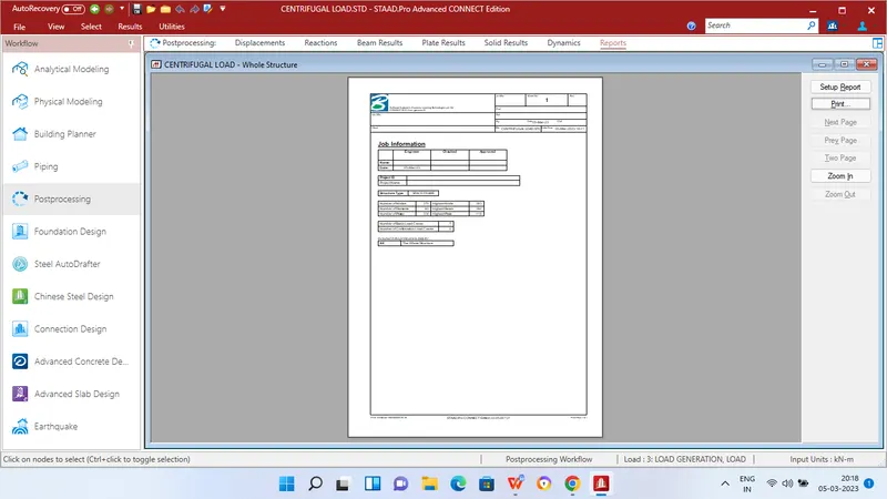
REPORT