Week 8 Challenge
1. Applying Load Exercise
Aim: To apply the loads for the structure modelled in previous exercise (Week 7 Challenge).
- Form a Load case as DL for Dead Load
- Apply Self weight
- Apply member load of 3 kN/m on the rafter
- Apply member load of 6 kN/m on the secondary beams
- Apply point load of 20 kN at node intersecting inclined member on the top chord.
- Form a Load case as LL for Live Load
- Apply member load of 4 kN/m on the rafter
- Apply member load of 7.5 kN/m on the secondary beams
- Form load combination 1.5DL+1.5LL
Steps:
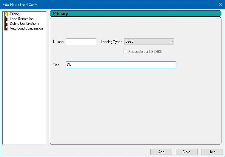
Form a Load case as DL for Dead Load
Analytical Modeling `=>` Loading `=>` Load Cases Details `=>` Add `=>` Loading Type - Dead and Title - DL `=>` Add
Apply Self weight
Analytical Modeling `=>` Loading `=>` DL `=>` Add `=>` Direction - Y and Factor - -1.05 `=>` Add
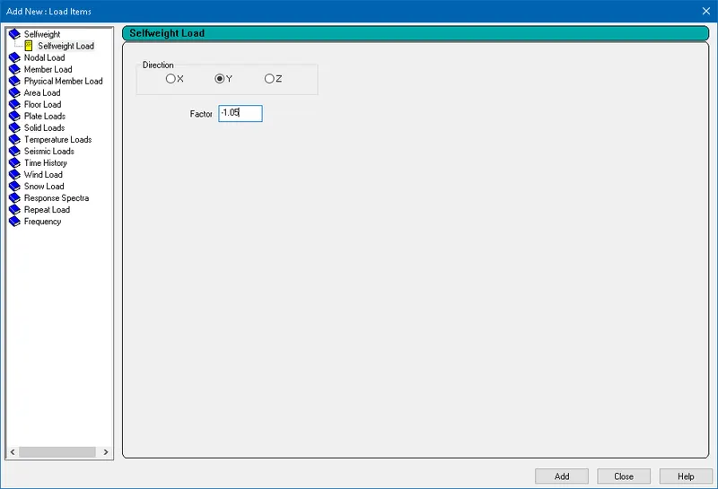
5% extra has been considered in self weight in order to compensate for the connections and unmodelled parts.
SELFWEIGHT Y -1.05 `=>` Assign To View `=>` Assign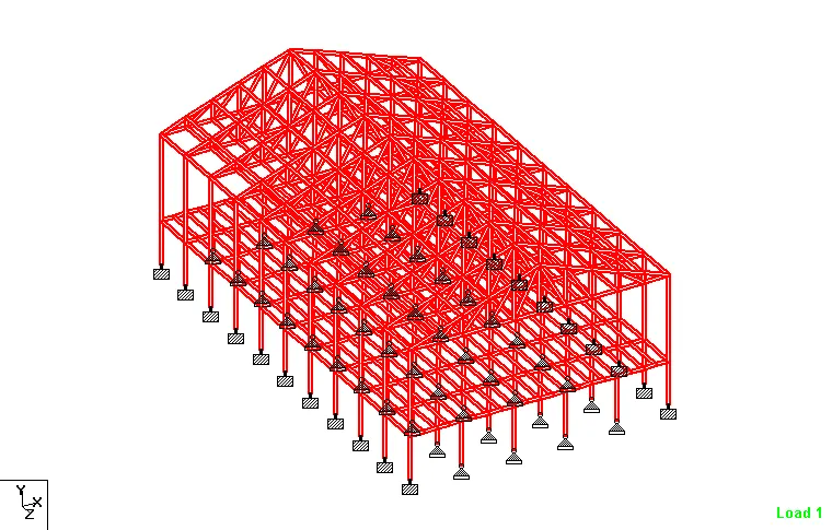
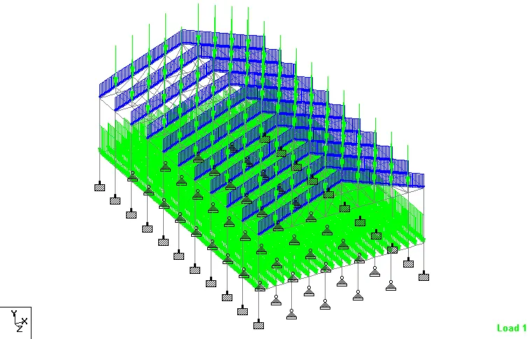
Apply member load of 3 kN/m on the rafter
Analytical Modeling `=>` Loading `=>` DL `=>` Add `=>` Uniform Force `=>` W1 - -3 kN/m and Direction - GY `=>` Add
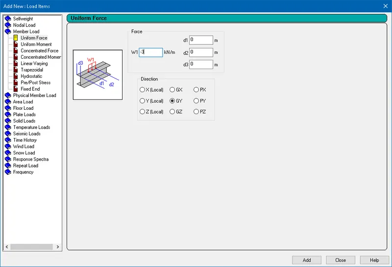
UNI GY -3 kN/m `=>` Select the Rafters `=>` Assign To Selected Beams `=>` Assign
Apply member load of 6 kN/m on the secondary beams
Analytical Modeling `=>` Loading `=>` DL `=>` Add `=>` Uniform Force `=>` W1 - -6 kN/m and Direction - GY `=>` Add
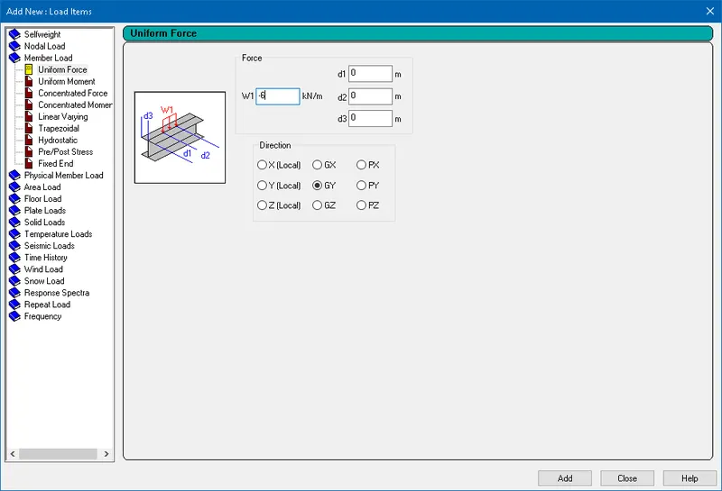
UNI GY -6 kN/m `=>` Select the Secondary members `=>` Assign To Selected Beams `=>` Assign
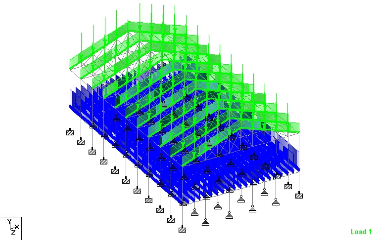
Apply point load of 20 kN at node intersecting inclined member on the top chord.
On the inclined member, 8 intersecting nodes are present. Hence, the 20 kN is divided by 8 nodes.
`20/8 = 2.5`kN
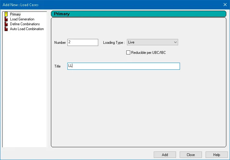
Form a Load case as LL for Live Load
Analytical Modeling `=>` Loading `=>` Load Cases Details `=>` Add `=>` Loading Type - Live and Title - LL `=>` Add
Apply member load of 4 kN/m on the rafter
Analytical Modeling `=>` Loading `=>` LL `=>` Add `=>` Uniform Force `=>` W1 - -4 kN/m and Direction - GY `=>` Add
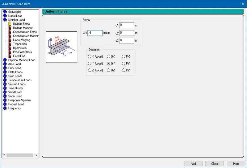
UNI GY -4 kN/m `=>` Select the Rafters `=>` Assign To Selected Beams `=>` Assign
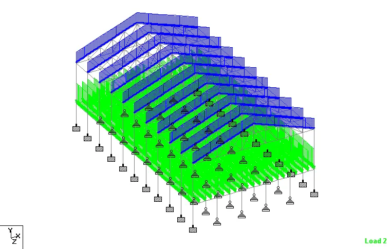
Apply member load of 7.5 kN/m on the secondary beams
Analytical Modeling `=>` Loading `=>` LL `=>` Add `=>` Uniform Force `=>` W1 - -7.5 kN/m and Direction - GY `=>` Add
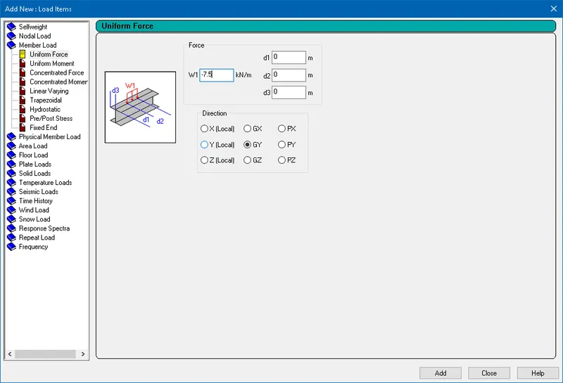
UNI GY -7.5 kN/m `=>` Select the Secondary members `=>` Assign To Selected Beams `=>` Assign
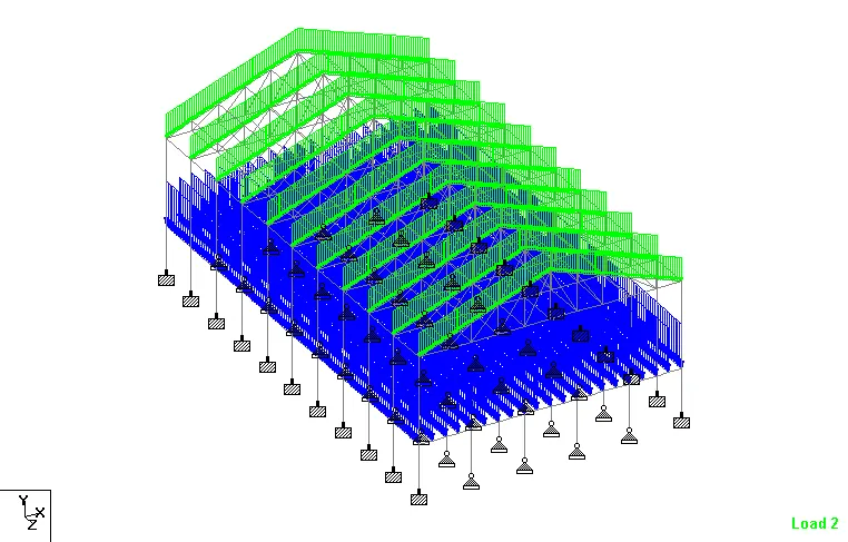
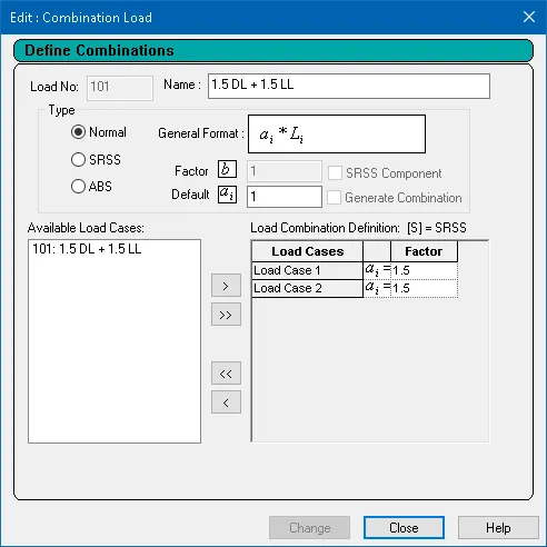
Form load combination 1.5DL+1.5LL
Analytical Modeling `=>` Loading `=>` Load Cases Details `=>` Add `=>` Define Combinations `=>` Name and Factor 1.5 `=>` Add
2. Find Maximum Force and Minimum Force for member and present the STAAD result.
Aim: To Run the analysis and to find following results on the member mentioned
- Run the analysis
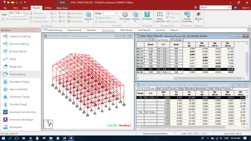
- Find the Maximum Moment in the Secondary beam for 1.5DL+1.5LL case
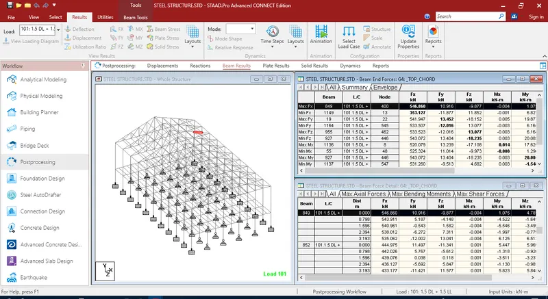
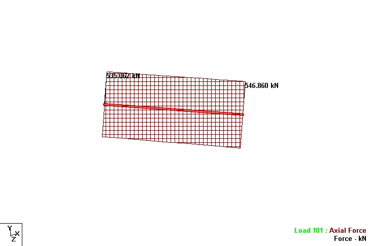
- Find the Maximum Axial force on the inclined bracing and identify the member having the maximum force for 1.5DL+1.5LL case
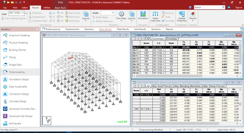
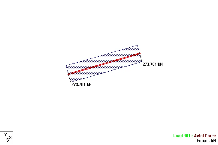
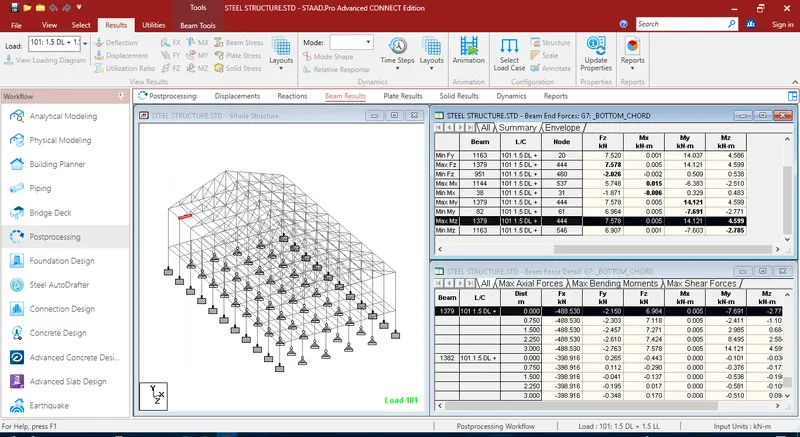
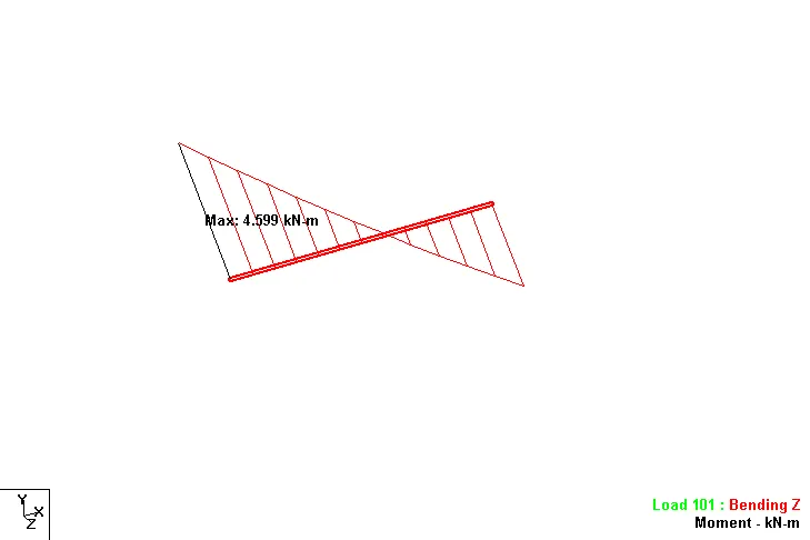
- Identify Bottom chord of Truss having Maximum shear Force & Maximum moment for 1.5DL+1.5LL case and present the values.
Steps:
Run the analysis
Menu bar `=>` Loading `=>` Analysis and Design `=>` Run Analysis
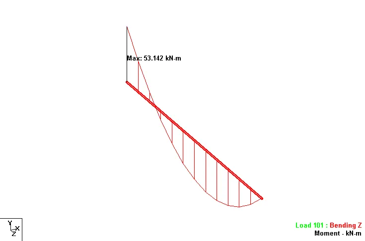
Find the Maximum Moment in the Secondary beam for 1.5DL+1.5LL case
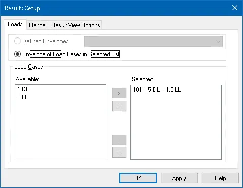
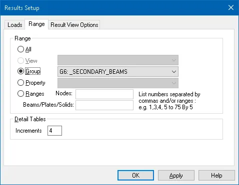
Post processing `=>` Results `=>` Select Load Case `=>` Load Cases - 101. 1.5 DL + 1.5 DL `=>` Range Tab `=>` Group `=>` Secondary beams `=>` OK
Find the Maximum Axial force on the inclined bracing and identify the member having the maximum force for 1.5DL+1.5LL case
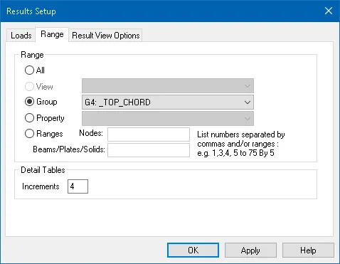
Post processing `=>` Results `=>` Select Load Case `=>` Load Cases - 101. 1.5 DL + 1.5 DL `=>` Range Tab `=>` Group `=>` Top Chord `=>` OK
Identify Bottom chord of Truss having Maximum shear Force & Maximum moment for 1.5DL+1.5LL case and present the values.
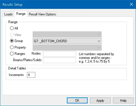
Post processing `=>` Results `=>` Select Load Case `=>` Load Cases - 101. 1.5 DL + 1.5 DL `=>` Range Tab `=>` Group `=>` Bottom Chord `=>` OK
3. View and Rectify the Warning, instabilities in the structure
Aim: To identify the Warnings and fix the same for the attached STAAD file and run the analysis.
Steps:
Utilities `=>` Analysis Output `=>` Warnings
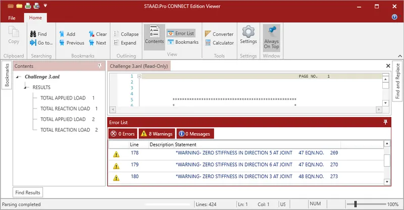
The warning zero stiffness is due to the inclined member connecting to the bracing middle are assingned as a Truss member
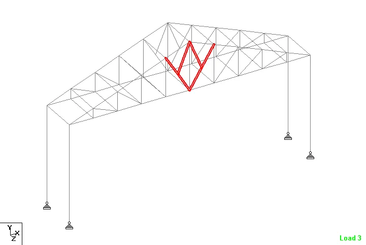
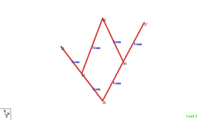
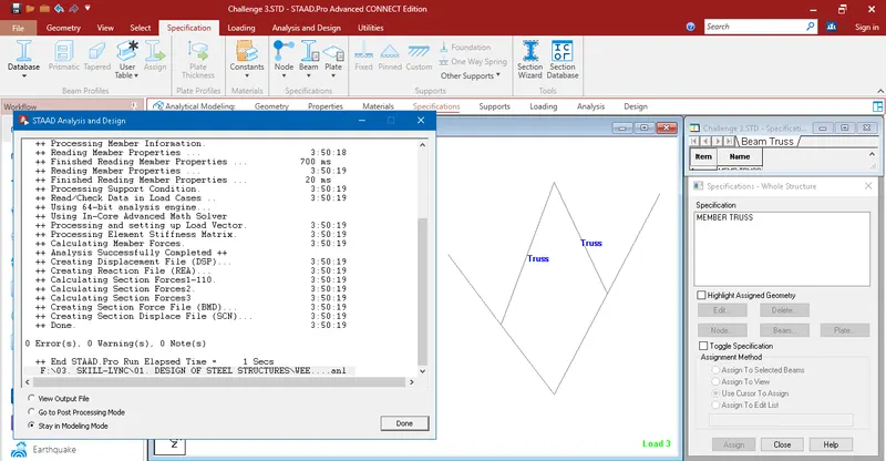
To avoid this warning, the truss member specification to be removed for the bottom inclined member as shown below.
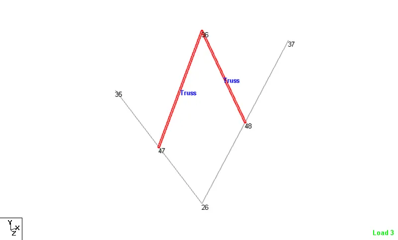
From this type of assigning, the bottom inclined member ll be made to take up the moments.
4. Design Parameter exercise
Aim: To apply Design parameter for structure modelled for the code IS800:2007.
- Effective Length Lx, Ly, Lz for beams, Truss elements
- Effective length factors Ky, Kz for Columns
- Apply other design parameters for respective members
Steps:
Effective Length Lx, Ly, Lz for beams, Truss elements
Bottom Chord
Analytical Modeling `=>` Design `=>` Define Parameters `=>` Lx `=>` 3
Analytical Modeling `=>` Design `=>` Define Parameters `=>` Ly `=>` 3
Analytical Modeling `=>` Design `=>` Define Parameters `=>` Lz `=>` 3
Top Chord
Analytical Modeling `=>` Design `=>` Define Parameters `=>` Lx `=>` 3.2
Analytical Modeling `=>` Design `=>` Define Parameters `=>` Ly `=>` 3.2
Analytical Modeling `=>` Design `=>` Define Parameters `=>` Lz `=>` 3.2
Main Beams
Analytical Modeling `=>` Design `=>` Define Parameters `=>` Lz `=>` 6.0
Truss members
For the truss members, conservatively instead of considering reduction in the length of the truss member, effective length is taken as full.
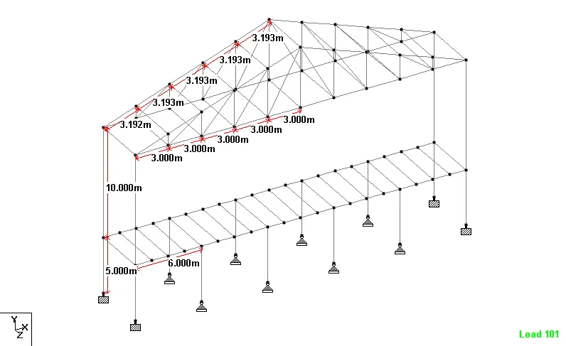
Effective length factors Ky, Kz for Columns
Analytical Modeling `=>` Design `=>` Define Parameters `=>` Ky `=>` 2
Analytical Modeling `=>` Design `=>` Define Parameters `=>` Kz `=>` 2
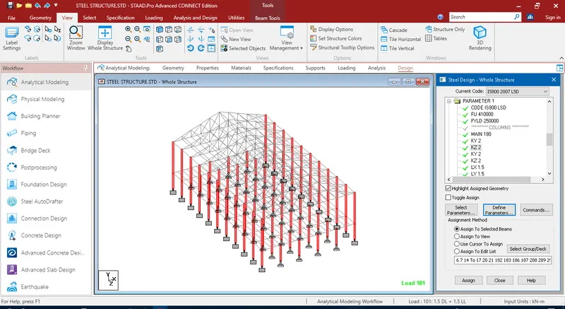
Since the column is not braced in any direction, conservatively, all the column's effective length fator Ky & Kz are 2.0.
Apply other design parameters for respective members
Analytical Modeling `=>` Design `=>` Define Parameters `=>` Main `=>` 180
For the pure compression member, slenderness limit is taken as 180 as per IS 800: 2007.
Analytical Modeling `=>` Design `=>` Define Parameters `=>` Ratio `=>` 1.0
For all the member, unity check limit is taken as 1.0.
Analytical Modeling `=>` Design `=>` Commands `=>` Take Off `=>` Add
In order to calculate the MTO of the modelled structure, take off command is used.
Analytical Modeling `=>` Design `=>` Commands `=>` Check Code `=>` Add
In order to analyse the modelled structure as per IS 800: 2007, Check Code command is used.