Week 12 Challenge
1. Isolated Footing
Aim: To design isolated footing for,
Column = 300 mm x 450 mm
Axial load = 1500 kN
Moment Mu = 150 kNm moment is reversible
Safe bearing capacity of the soil = 200 kN/m2 at a depth of 1 metre from ground level.
Use M 25 and Fe 415 for the footing.
Steps:
After opening the Staad foundation advanced, the proceed with the design of foundation,
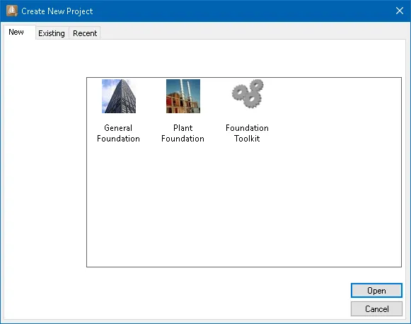
New `=>` General Foundation
Setting up the grid
General Foundation mode `=>` Foundation Plan `=>` Linear Grid setup
Required number of grids where the footing is positioned is generated.
General Foundation mode `=>` Foundation Plan `=>` Column position
Makes the coordinates of the position of column
General Foundation mode `=>` Foundation Plan `=>` Column Dimension
Provide the size of the footing in the followed box.
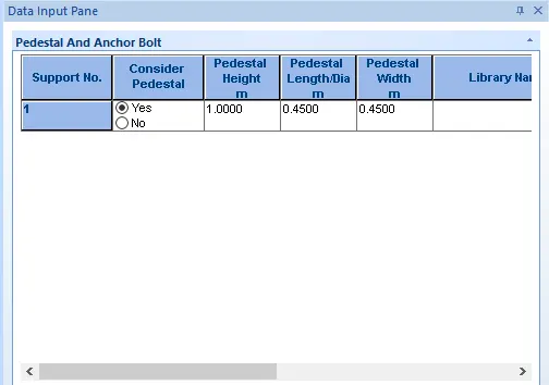
General Foundation mode `=>` Foundation Plan `=>` Pedestal and Anchor bolt
Pedestal height, Pedestal length and width is provided
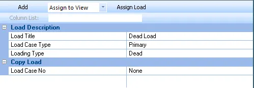
General Foundation mode `=>` Loads & Factors `=>` Create New Load Case
Load title and loading type is given and clicked Add
General Foundation mode `=>` Loads & Factors `=>` Add a Column Reaction Load
Reaction load Fy = 1500 kN & Moment Mz = 150 kNm
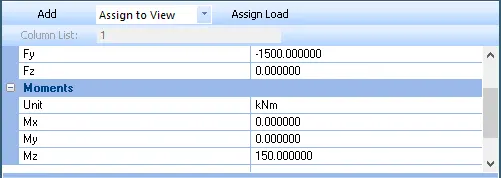
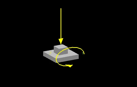
General Foundation mode `=>` Loads & Factors `=>` Generate Load Combinations
To have the load combinations, generate load combination is used to automatically generate the load combinations.
General Foundation mode `=>` Job Setup
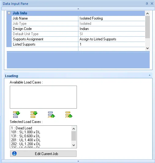
The Job name, type and design code is selected as shown below.
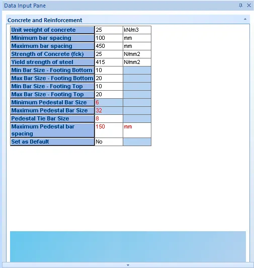
General Foundation mode `=>` Isolated Footing Job `=>` Design Parameters `=>` Concrete & Reinforcement
The design parameter for the concrete and reinforcement is shown below,
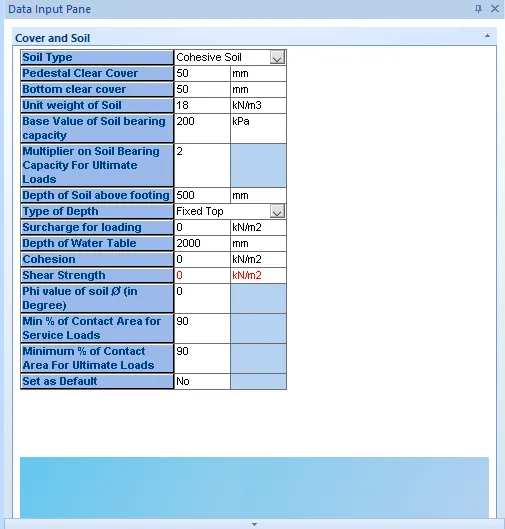
General Foundation mode `=>` Isolated Footing Job `=>` Design Parameters `=>` Cover & Soil
The design parameter for the cover and soil is shown below,
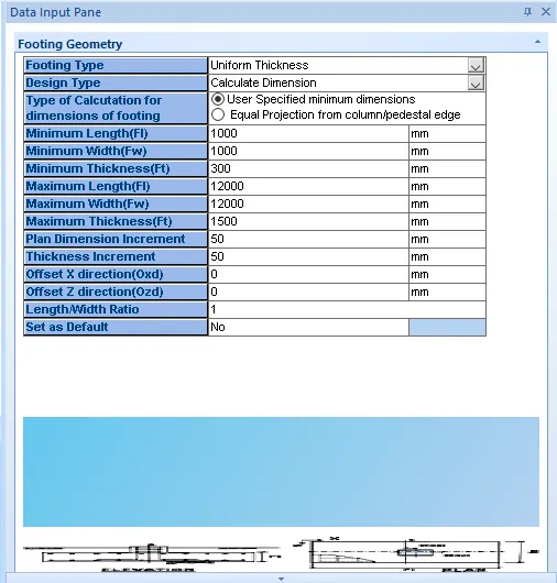
General Foundation mode `=>` Isolated Footing Job `=>` Design Parameters `=>` Footing Geometry
The design parameter for the footing geometry is shown below,
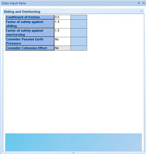
General Foundation mode `=>` Isolated Footing Job `=>` Design Parameters `=>` Sliding & Overturning
The design parameter for the sliding & overturning is shown below,
General Foundation mode `=>` Isolated Footing Job `=>` Design Parameters `=>` Design
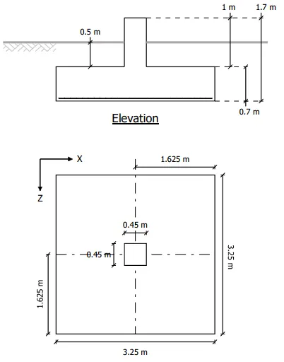
The design parameter Design is used to analyse the specified isolated footing and the output is interpreted.
The summary of the combined footing design is shown as given below.

Check for Gross bearing pressure
Footing Length, L = 3.25 m
Footing Breadth, B = 3.25 m
Soil weight = `[(3.25 m xx 3.25 m) - (0.45 m xx 0.45 m)] xx 0.5 m xx 18 kN/m3`
= 93.24 kN
Footing weight = `[(3.25 m xx 3.25 m xx 0.7) + (0.45 m xx 0.45 m xx 1.0 m)] xx 25`
= 189.91 kN
Unfactored, `P_s = P + Soil weight + Footing weight`
= 1500 kN + 93.24 kN + 189.91 kN
`P_s = 1783.15 kN`
Factored Load, `P_u = 2496.405 kN`
Unfactored, `M_s = 150 kNm`
Factored, `M_u = 210 kNm`
Area of Footing, `A = 3.25 xx 3.25 = 10.563 m^2`
Section modulus,` Z = (b d^2)/6` = `(3.25 xx 3.25^2)/6`
Z = 5.72 `m^3`
`q_max = P_s /A + M_s/Z`
= `1783.15/10.563 + 150/5.72`
`q_max = 195.03 kN/m^2`< SBC Hence, Provided area is safe
`q_min = P_s /A - M/Z`
= `1783.15/10.563 - 150/5.72`
`q_min = 142.6 kN/m^2` < SBC Hence, Provided area is safe and no uplift is present.
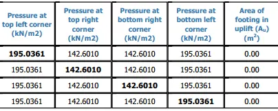
Calculation of Ultimate bearing pressure
Factored Load, `P_u = 2496.405 kN`
Factored Moment,`M_u = 210 kNm`
Area of Footing, `A = 3.25 xx 3.25 = 10.563 m^2`
Section modulus,` Z = (b d^2)/6` = `(3.25 xx 3.25^2)/6`
Z = 5.72 `m^3`
`Q_max = P_u /A + M_s/Z`
= `2496.405/10.563 + 210/5.72`
`Q_max = 273.05 kN/m^2`
`Q_min = P_u /A - M/Z`
= `2496.405/10.563 - 210/5.72`
`Q_min = 199.62 kN/m^2`
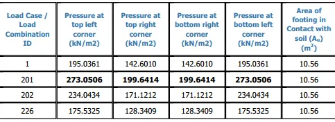
Calculation of Moment using the Ultimate Pressure
Moment, `M_max = (Q_max xx L^2)/2`
`M_max = (273.05 xx ((3.25-0.45)/2)^2)/2`
`M_max = 267.59 kNm`
One Way Shear
Distance of the critical section = `3.25/2 - 0.45/2 - 0.64`
= `0.76 m`
Shear for 1m footing width , = `Q_max xx 0.76 xx 1m width`
= `273.05 xx 0.76 xx 1m width`
= `207.52 kN`
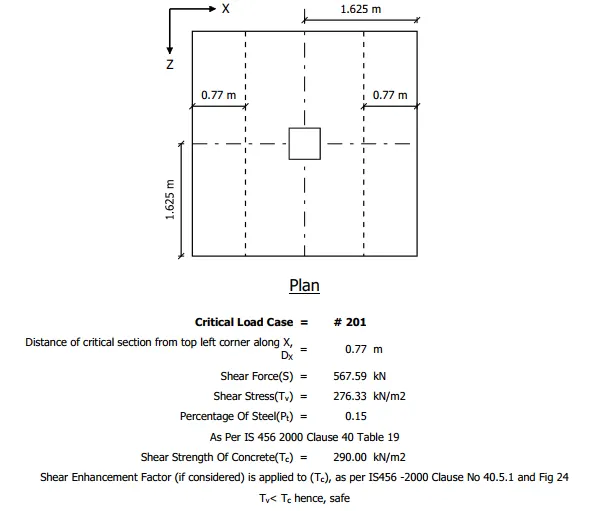
Two Way Shear
Distance of the critical section = `[(3.25 xx 3.25) - (1.094 xx 1.094)]`
= `9.37 m^2`
Shear force , = `Q_max xx critical punching area`
= `273.05 xx 9.37
= `2557.29 kN`
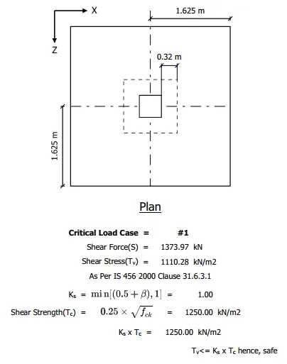
Resisting Moment
Total Load = Soil weight + Concrete weight
= 93.24 kN + 189.91 kN
= 283.15 kN
Moment due to Soil & Concrete = `283.15 xx 3.25/2`
= `283.15 xx 3.25/2`
= `460.11 kNm`
Moment due to Compression = `1500 xx 3.25/2`
= `2437.5 kNm`
Restoring Moment, R = 460.11 + 2437.5
R = `2897.61 kNm`
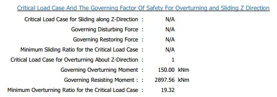
The results with manual calculation has been presented here as above.
2. Combined Footing
Aim: To design isolated footing for,
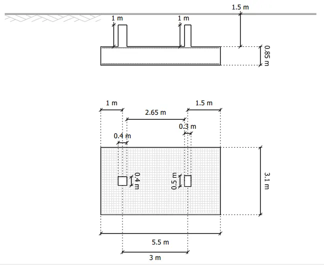
Column C1 = 400 mm x 400 mm
Column C2 = 300 mm x 500 mm
Axial load C1 = 800 kN
Axial load C2 = 1500 kN
Columns c/c distance = 3 m
Moment Mu = 150 kNm moment is reversible
Safe bearing capacity of the soil = 200 kN/m2 at a depth of 1.5 metre from ground level.
Use M 25 and Fe 415 for the footing.
Steps:
After opening the Staad foundation advanced, the proceed with the design of foundation,
New `=>` General Foundation
Setting up the grid
General Foundation mode `=>` Foundation Plan `=>` Linear Grid setup
Required number of grids where the footing is positioned is generated at column c/c of 3m.
General Foundation mode `=>` Foundation Plan `=>` Column position
Makes the coordinates of the position of column
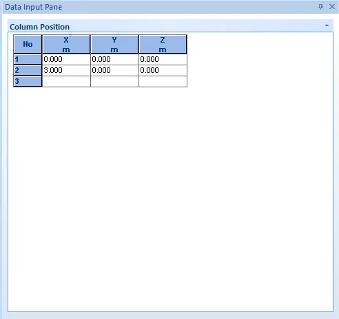
General Foundation mode `=>` Foundation Plan `=>` Column Dimension
Provide the size of the footing in the followed box.
General Foundation mode `=>` Foundation Plan `=>` Pedestal and Anchor bolt
Pedestal height, Pedestal length and width is provided
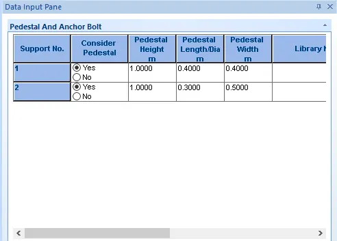
General Foundation mode `=>` Loads & Factors `=>` Create New Load Case
Load title and loading type is given and clicked Add
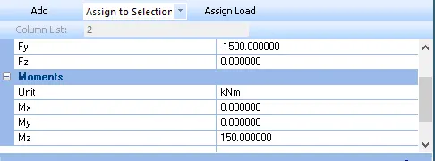
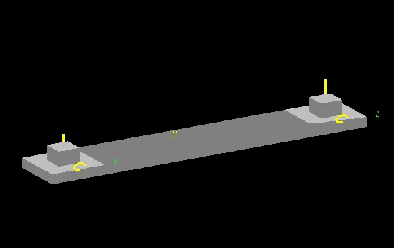
General Foundation mode `=>` Loads & Factors `=>` Add a Column Reaction Load
C1 Reaction load Fy = -800 kN & Moment Mz = 150 kNm
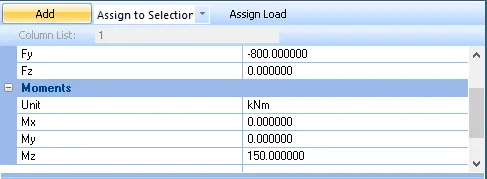
C2 Reaction load Fy = -1500 kN & Moment Mz = 150 kNm
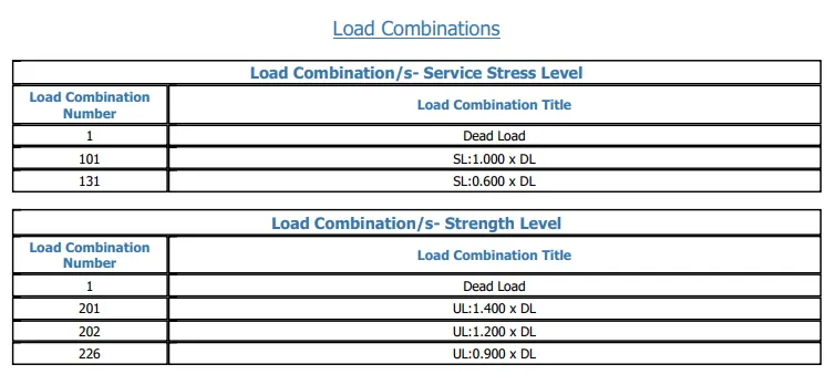
General Foundation mode `=>` Loads & Factors `=>` Generate Load Combinations
To have the load combinations, generate load combination is used to automatically generate the load combinations.
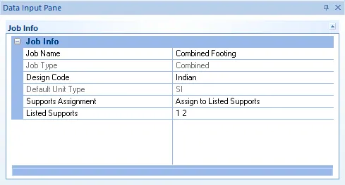
General Foundation mode `=>` Job Setup
The Job name, type and design code is selected as shown below.
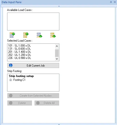
Again Edit current job, strip footing is selected and applied for the selected footing.
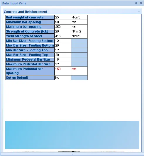
General Foundation mode `=>` Isolated Footing Job `=>` Design Parameters `=>` Concrete & Reinforcement
The design parameter for the concrete and reinforcement is shown below,
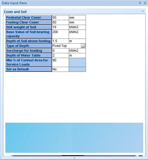
General Foundation mode `=>` Isolated Footing Job `=>` Design Parameters `=>` Cover & Soil
The design parameter for the cover and soil is shown below,
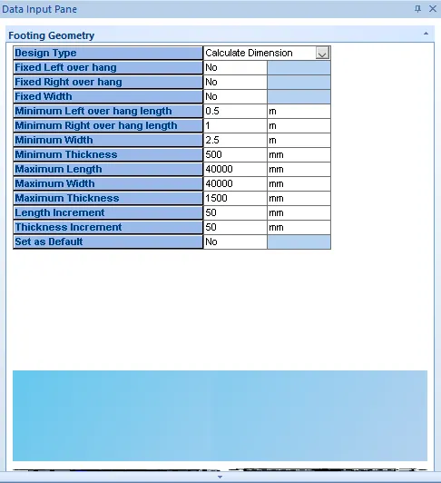
General Foundation mode `=>` Isolated Footing Job `=>` Design Parameters `=>` Footing Geometry
The design parameter for the footing geometry is shown below,
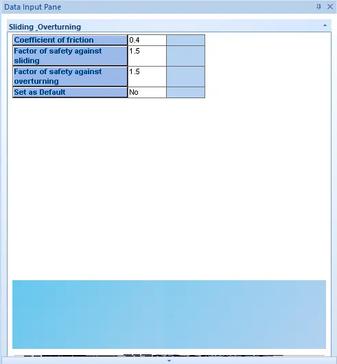
General Foundation mode `=>` Isolated Footing Job `=>` Design Parameters `=>` Sliding & Overturning
The design parameter for the sliding & overturning is shown below,
General Foundation mode `=>` Isolated Footing Job `=>` Design Parameters `=>` Design
The design parameter Design is used to analyse the specified isolated footing and the output is interpreted.
The summary of the combined footing design is shown as given below.

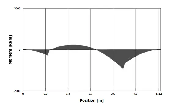
Bending moment drawing of the combined footing
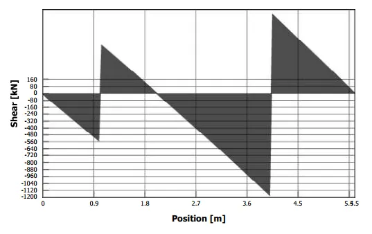
Shear force drawing of the combined footing