Week 8 - Challenge 6 - Core & Cavity Design
CORE AND CAVITY DESIGN
INTRODUCTION:
Import the switch bezel component designed and create the parting surface, parting line for the component. Create the core and cavity blocks for the switch bezel component.
OBJECTIVE:
Create the core and cavity blocks for the switch bezel designed.
TOOLING AXIS:
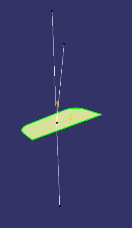
A dummy axis is created for reference, This is a normal line which i construct by analysing the best possible direction for the draft. Taking the dummy axis as as reference, intersect the class A surface along the different axis, check for possible places where the part might face difficulties while ejecting the componenet from the mold. using the intersection lines will be created along the inclined walls, these lines are used for creation of tooling axis by Bisecting Method.
DRAFT ANALYSIS:
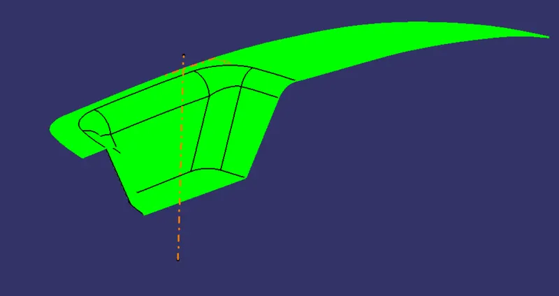
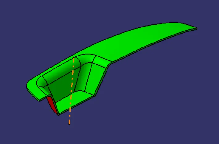
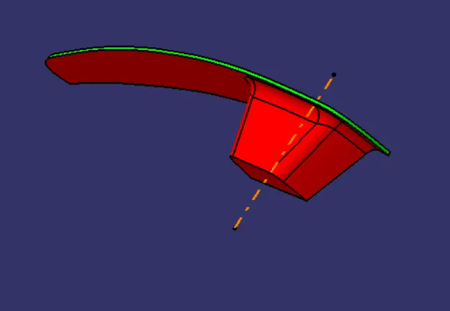
No parts can be ejected from the tool if it is having a straight 90degree profile from its base surface. A small draft angle is provide to component in order to get an easy removal from the tool. Draft analysis technique is used to analyze whether our part model created is manufacturable based on the draft condition applied. To start the draft analysis, we will go to insert and click on the option called analysis. Select the Feature Draft Analysis, click on Quick Analysis option on mode. Under direction we will choose the icon with the symbol of compass on it. Place it o the tooling axis.
1. DRAFT ON CLASS A:
2. FINAL DRAFT:
CORE AND CAVITY DESIGN:
PARTING SURFACE:
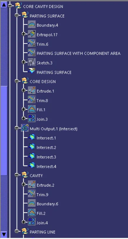
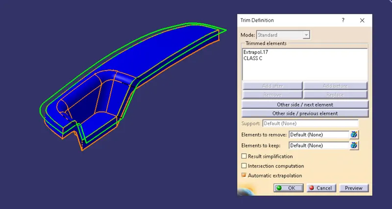
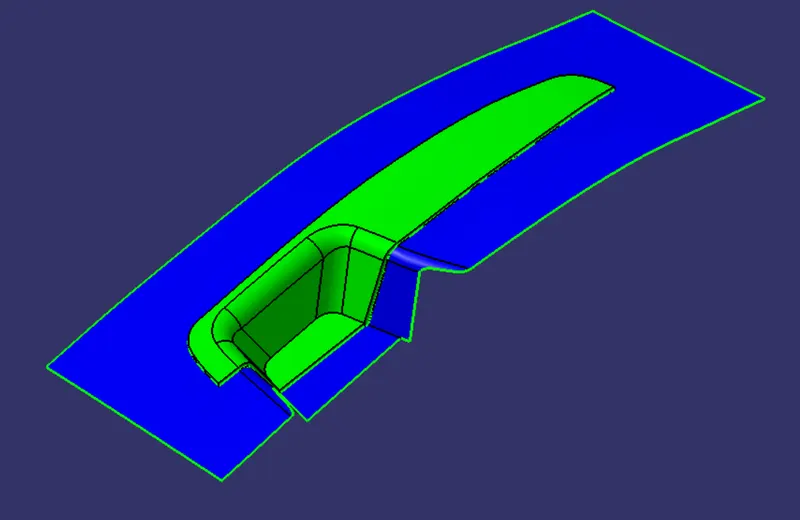
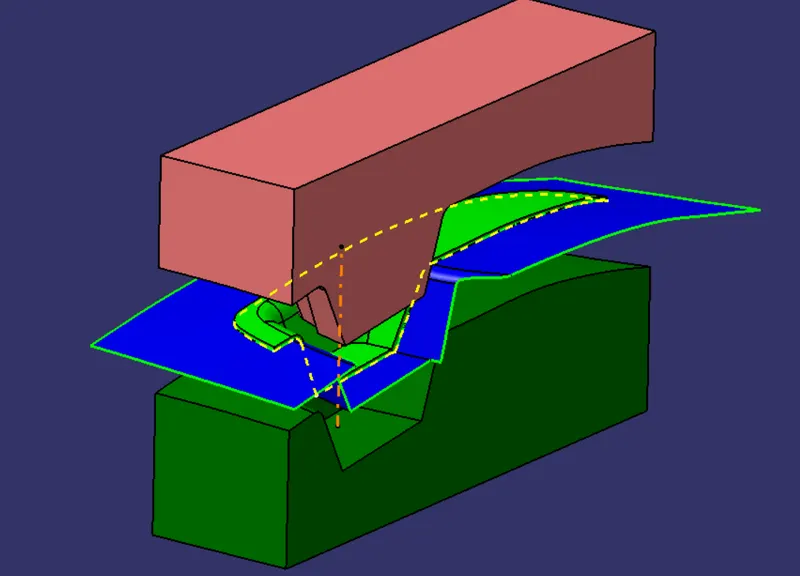
Extrapolate the class A surface and trim it with the class C surface.
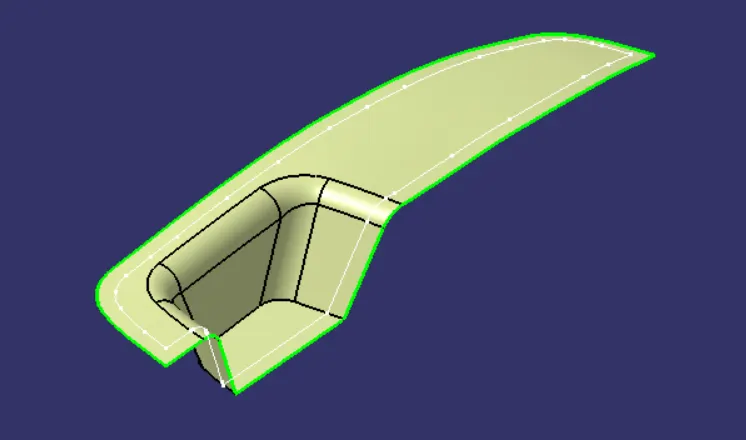
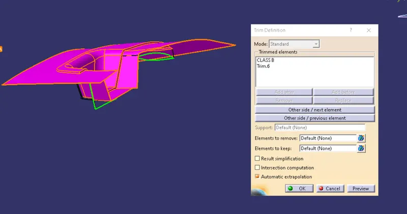
Trim the above surface with the class B to get the parting surface with component area.
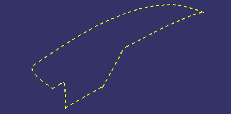
Create the parting line by intersecting the join of class A & C and class B surface.
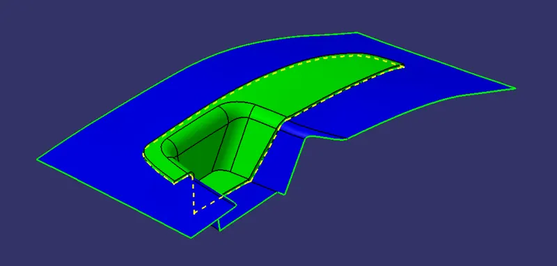
Split the parting line with the parting surface with component area to get the final parting surface.
CORE DESIGN:
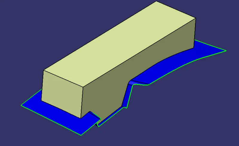
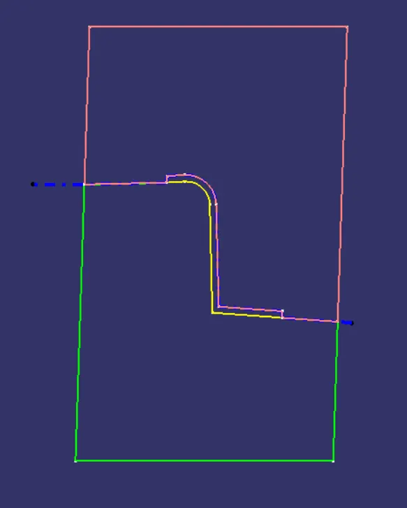
Draw a sketch on zx axis, make sure the sketch fit inside the parting surface.
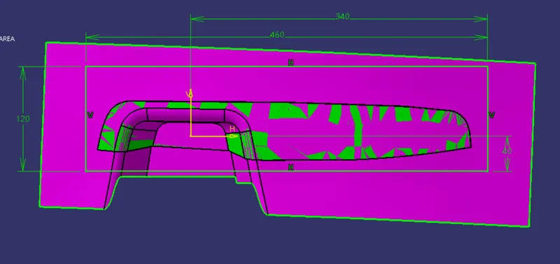
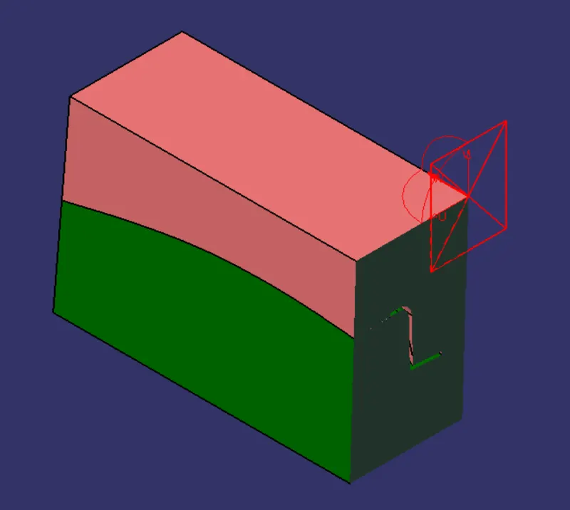
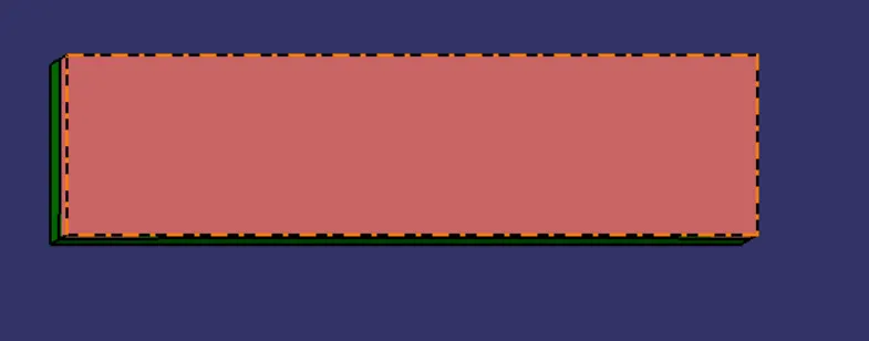
Extrude the sketch along the tooling axis and trim it with the parting surface. Fill the open surface and join it with the extrude, convert it to close surface.
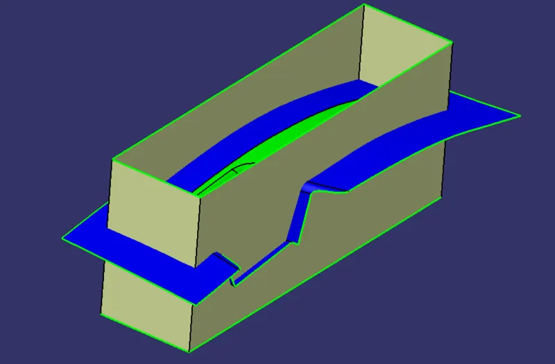
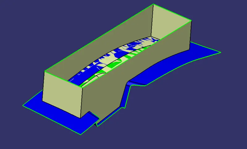
CAVITY DESIGN:
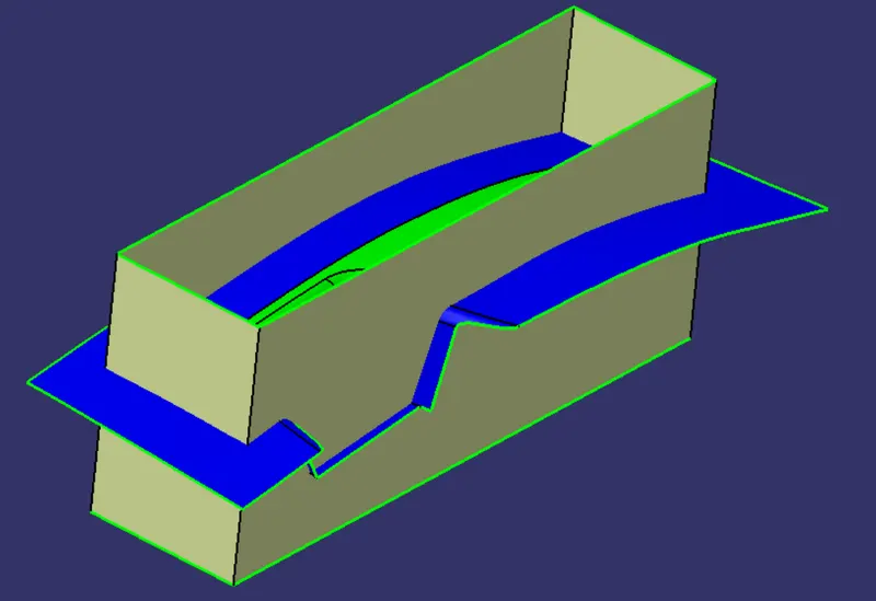
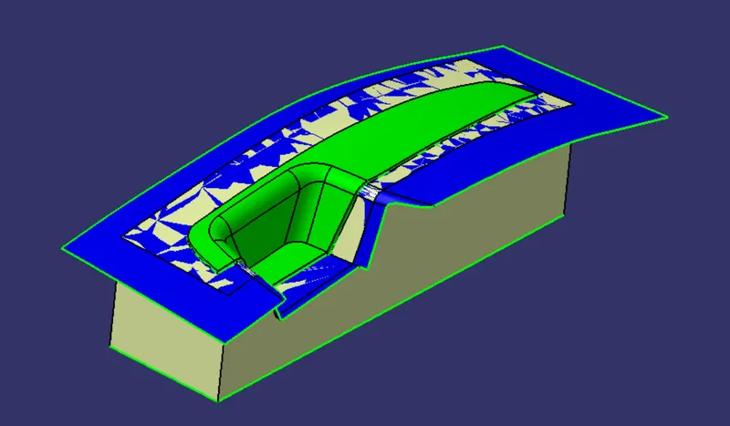
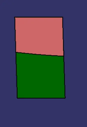
Extrude the sketch along tooling axis downwards and trim it with the parting surface. Fill the open surface and join it with the extrude and convert it to close surface to create the cavity block.
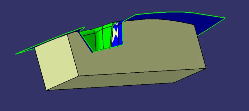
FINAL COMPONENT:
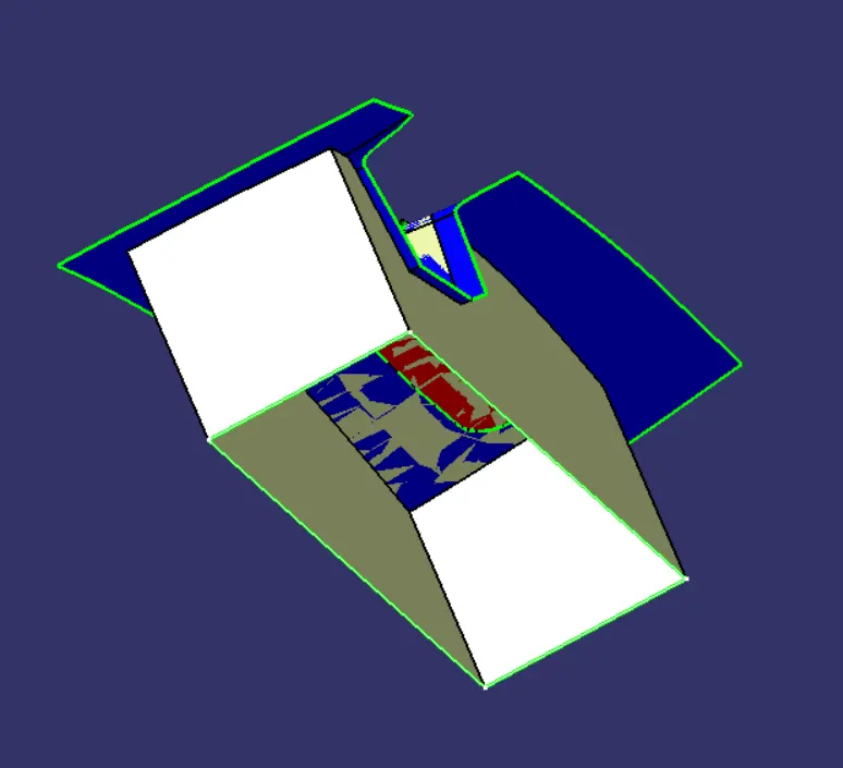
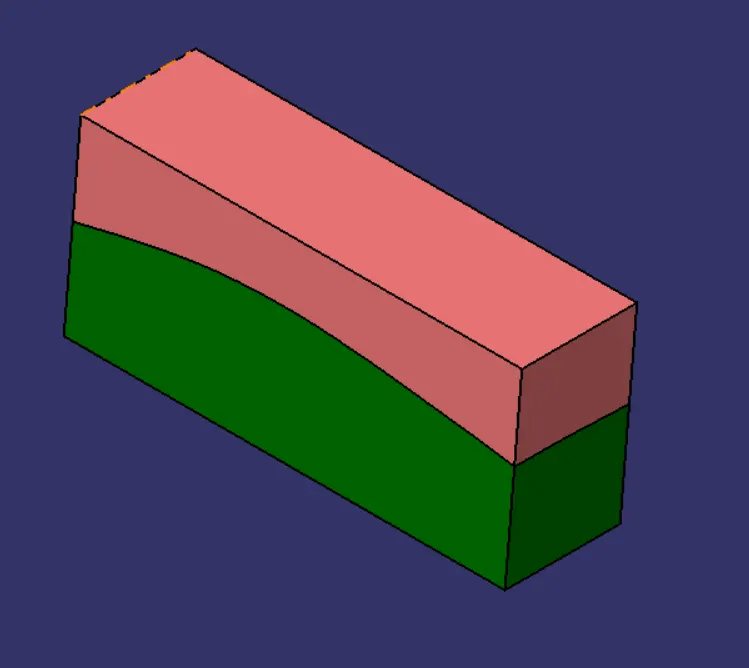
The core and cavity blocks are created. Check for the intersection to confirm the blocks.
VIEWS:

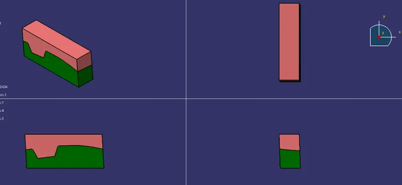
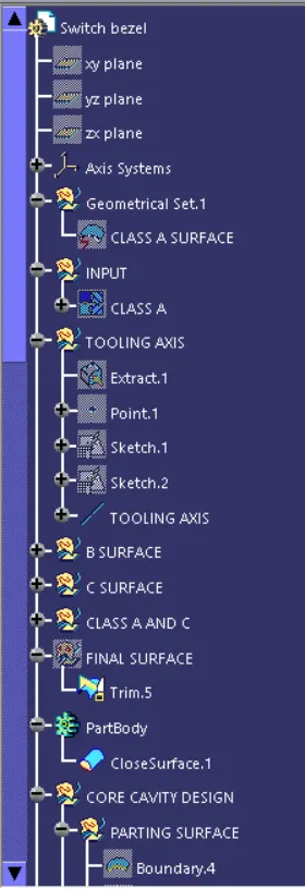
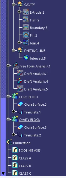
TREE STRUCTURE: