Week 8 - Challenge 6 - Core & Cavity Design
AIM- Create the Core and cavity blocks for the switch bezel.
The core and cavity are the two halves of the mould where the hot molten plastic material is injected into the core and cavity and the gap between the core and cavity is filled with the hot molten material during injection molding process and then hardened into final shape.
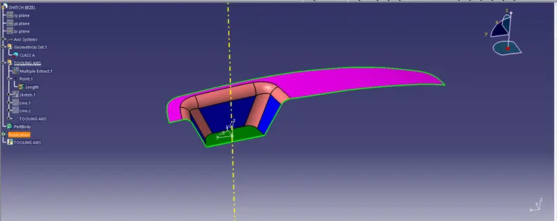
Construction of tooling axis
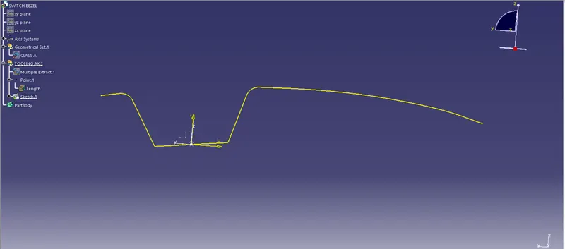
Bisecting lines are drawn for the construction of Tooling Axis.
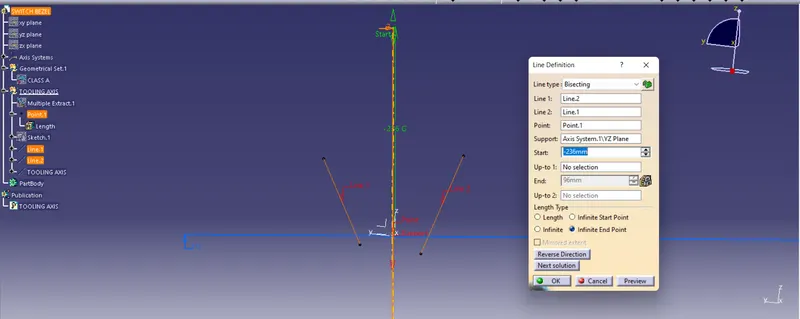
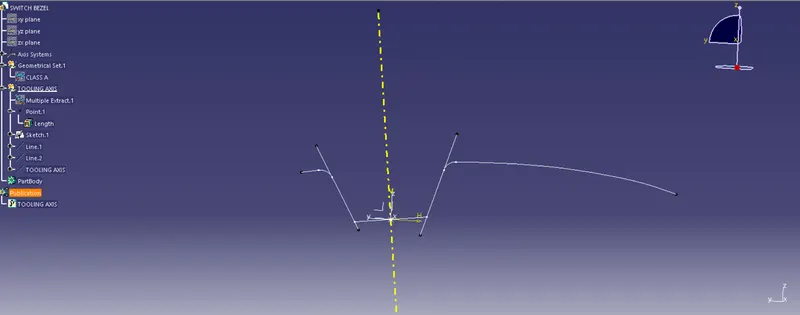
Tooling axis creation
- A Surface in XY plane is extracted and drawn perpendicular line and given the draft angle of 0.5-3 degree.
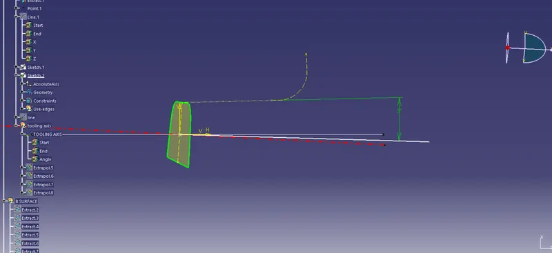
- Tooling Axis
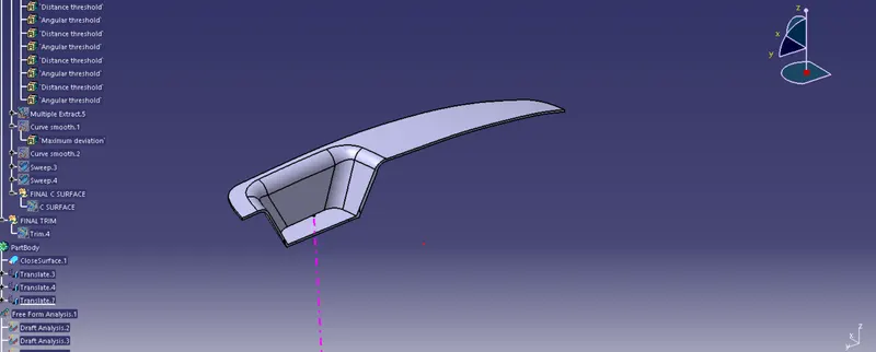
SWITCH BEZEL (MOULD)
Closed surface switch bezel, which will be the final component (mould) after the injection moulding process.
CREATION OF CORE & CAVITY BLOCK
The core is the raised part of the mold and the cavity is the recessed part of the mold.
The cavity and core in a typical plastic injection molding machine of an injection mold are the molding parts of the mold and play a key role in the shape of the molded part.
STEPS FOR THE CREATION OF CORE
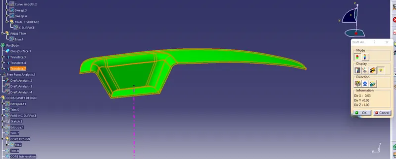
- First check the draft analysis of the component.
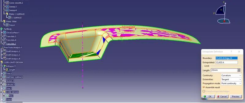
- Extrapolate the class A surface.
- Trim the CLASS A and CLASS C surface.
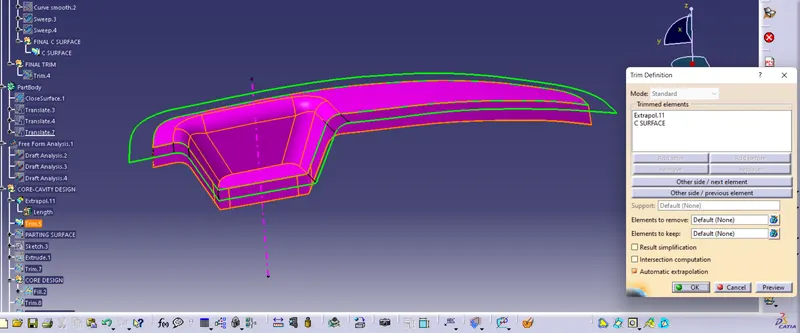
- To get the parting surface of Core and the cavity block, the trim of Class A & C as finally trimmed by Class B surface.
PARTING SURFACE: During injection moulding, core and cavity is pressed against each other tightly to create hollow space and avoid leaking of material. The surface where the two halves are joined is called parting surface.
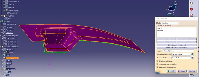
- Rectangular sketch is drawn on the XY-Plane for the purpose of extrusion of wall of core and cavity block.
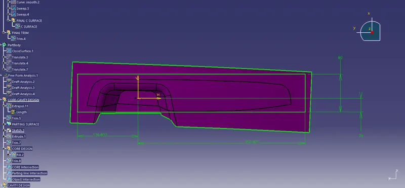
- Extrude walls for Blocks of core & cavity.
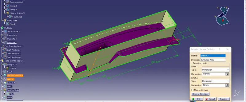
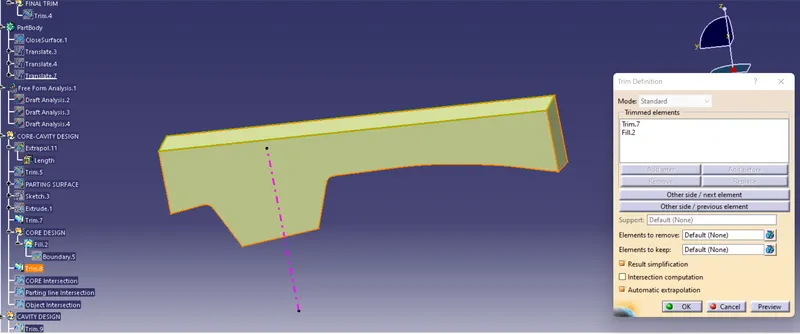
- Now Trim the extruded surface and the parting surface to get the Core block .
- Then the top walls are filled by using boundary and fill command.
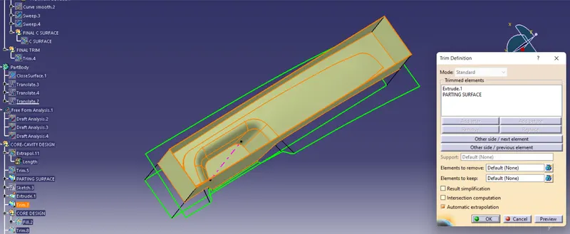
CORE BLOCK
- Same step was repeated and trimmed the other side of rhe parting surface and extruded wall surface to get the cavity block.
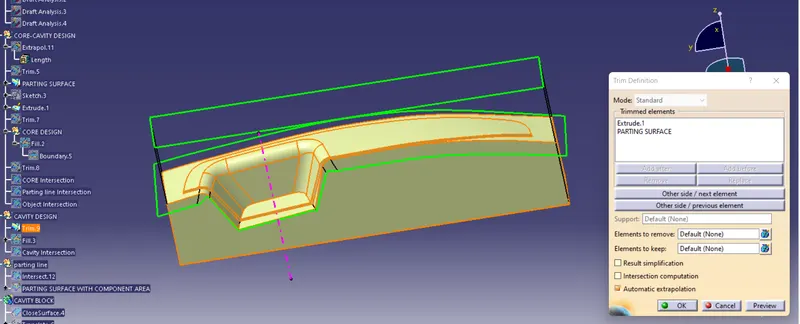
CAVITY BLOCK
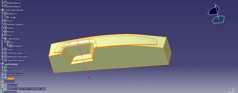
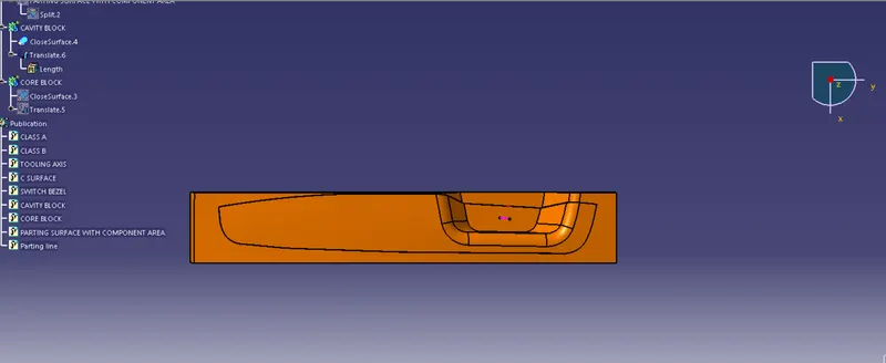
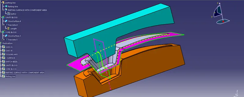
Core and cavity Blocks
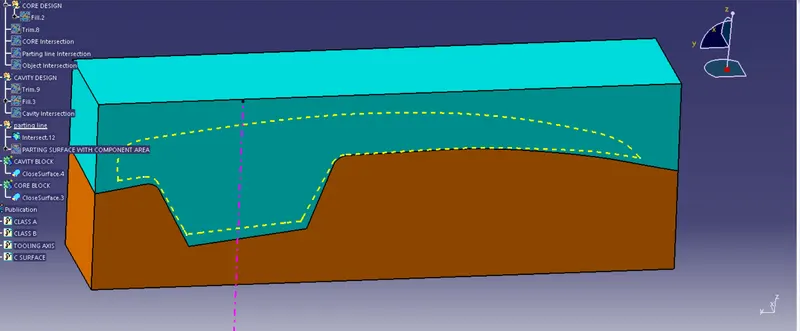
PARTING LINE
- A Parting line is the line of separation on the plastic part where the two halves of the plastic injection mold meet.
- This line is drawn by the intersection command.
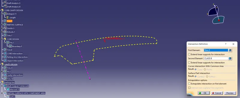
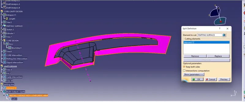
- Now we get the final parting surface by splitting the parting surface and the intersection line (parting line).
- Finally Intersection is taken on the YZ-Plane by taking tooling axis as the reference. To check the position or any overlapping of core, cavity and parting surface.
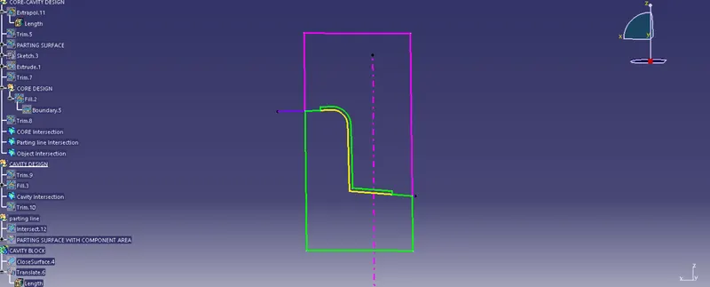
- By the Translate command some gap is given between the surfaces for the clear vision.
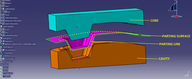
FRONT VIEW OF CORE-CAVITY BLOCKS
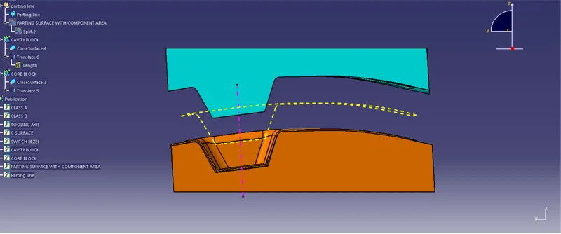
SIDE VIEW
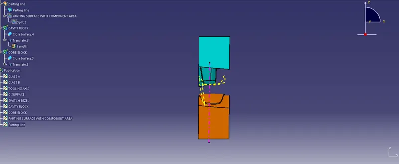
TOP VIEW OF CORE BLOCK
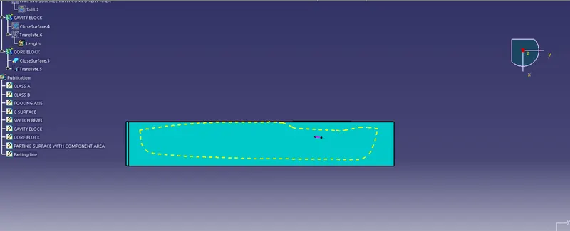
TOP VIEW OF CAVITY BLOCK
ISOMETRIC VIEW
DRAFT ANALYSIS OF FINAL SURFACE BODY
PROCEDURE
- First the class – A surface is checked before creating the Class –B&C surface and finally the solid body must be analysed. Both can be done by following the below procedures.
- By changing the view mode to custom view parameters – Material mode then the feature draft analysis is enabled.
- Then the compass activated and placed on the tooling axis by dragging the pointer and then locked it.
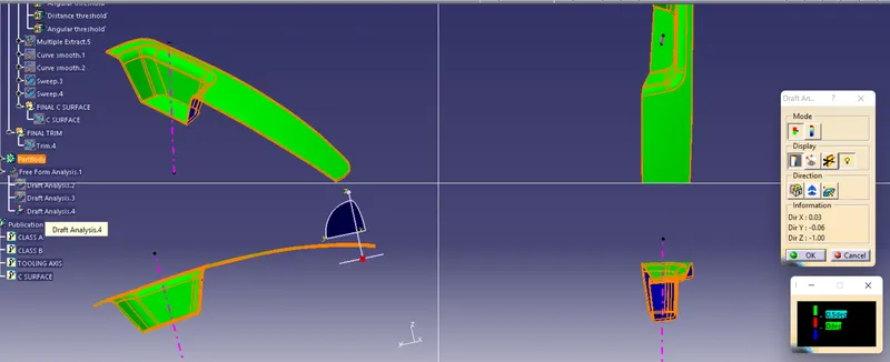
- Then, by selecting the quick analysis mode, the nominal draft value will be 3 degrees and checked for the component's draft angle.
- The green colour area shows that it satisfies the 3-degree draft angle. If not satisfied then by using the Running point tool the area is measured and then altered to get a successful draft for the created tooling direction.
- In plastic design we can keep our draft angle value from 0.5 to 3 degree.
- here I got complete green in 0.5 degree analysis.
DRAFT ANALYSIS OF THE CLOSED SURFACE PART BODY
CONCLUSION
Here I've gained knowledge about core and cavity design , parting surface, parting line for a switch bezel.