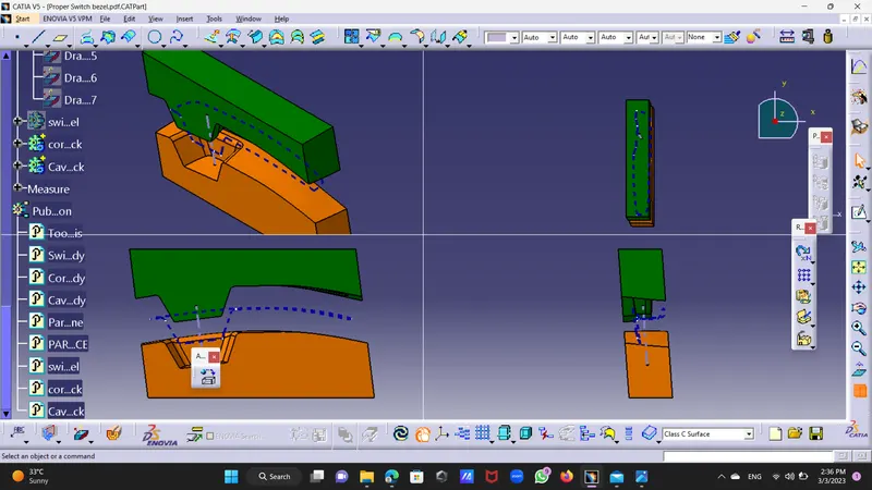
Week 8 - Challenge 6 - Core & Cavity Design
Assignment 26
Report:-
switch Bezel Core and Cavity :
Step 1:Took previously made Switch Bezel from on draft analysis had performed by 2.7 deg.
Step 2:Made new geonatrical set and named it as Core and Cavity ,sub geomatriacal set named it parting surface.
Parting Surface:-
Unhide extrapolated class A Surface and Class C Surface,Class B Surface.Trimed out Class C Surface with Extrapolated Class C Surface and Then Class Class B Surface,
the Surface above the class B Surface is core surface.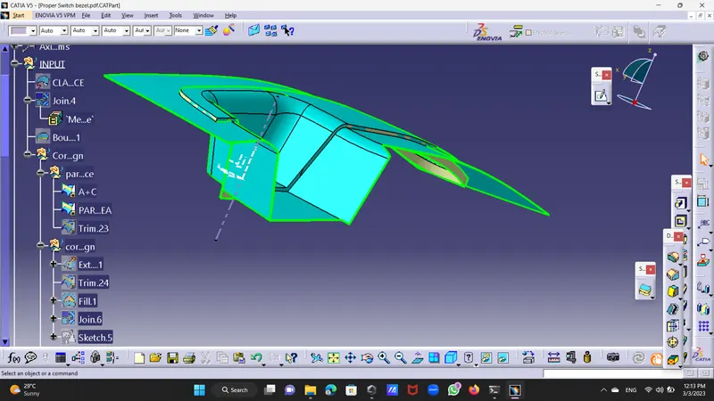
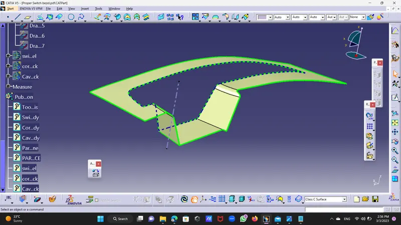
Core Design:
Step 3:Took position Sketch and XY Plane and origin as point drew a rectangle and constrained it well by taking care
that rectangle will not go beyond the parting surface and extrude it by 100mm distance form both side.
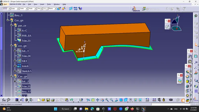
Trimed parting Surface with Extrude and so got upper design is core design.creat boudry on upper edge and filled it with fill command.
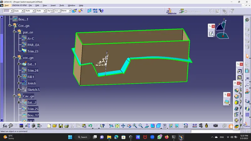
Solid Form of Core:
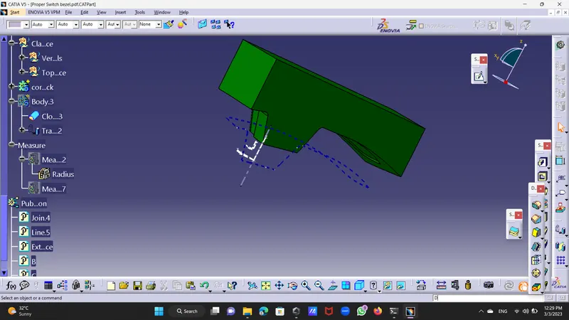
Step 4:Go to the part design and insert a body and chossed close body option took core portion and convert it to core solid.
Cavity Design:
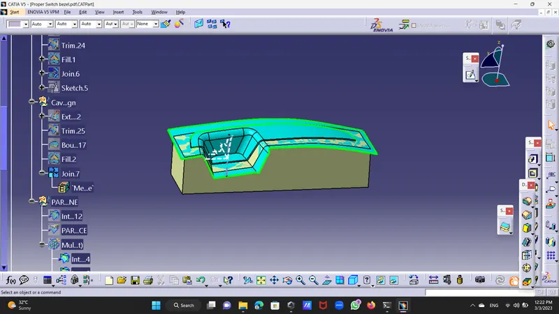
Step 5:Took new geomatrical set named it as cavity, took same sketch as above and extrude it up to 100mm and trimed with Class B Surface.
Took boundry and filled lower Surface with fill command.jion them properly .
Solid Body:
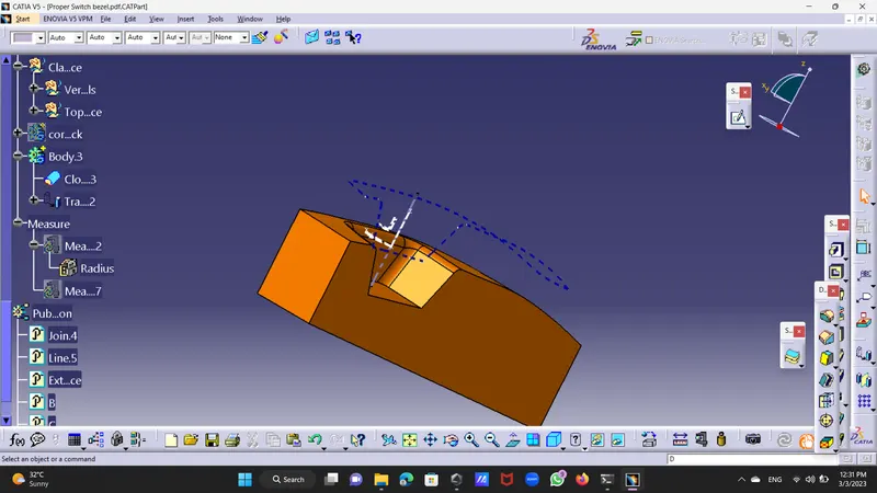
Step 6:Inset new body named it cavity desing and go to the part design and choosed a closed body option and convert cavity surface to solid.
Intersection:
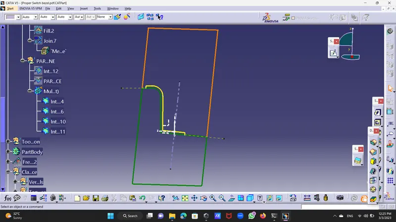
Step 7:Took intesection from tool bar and intersect ZX Plane with core and parting surface and cavity.
blocked colored by red
parting impression with yelow colour
parting line with blue colour.
Parting Line:
step 8:Took intersection of Class A+C Surface and Class B Surface and Split it outer surface obtained is known by parting surface.
this is real parting surface which trmed out by sharp tool after manufacturing done.
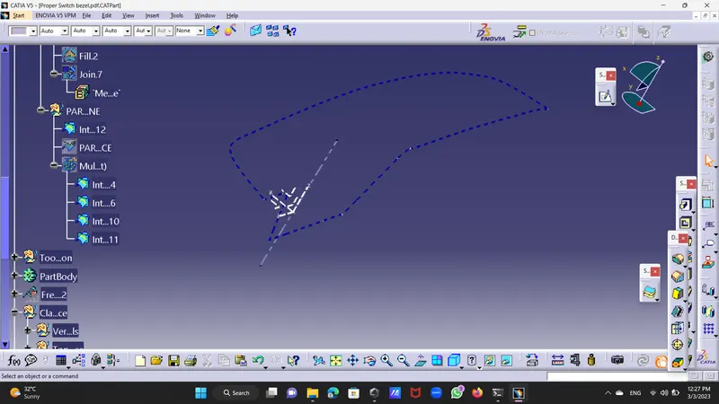
Step 9:Go to the part design and take translation by distance chossed direction ans axis direction and shfted it with distance 50mm (+,-)
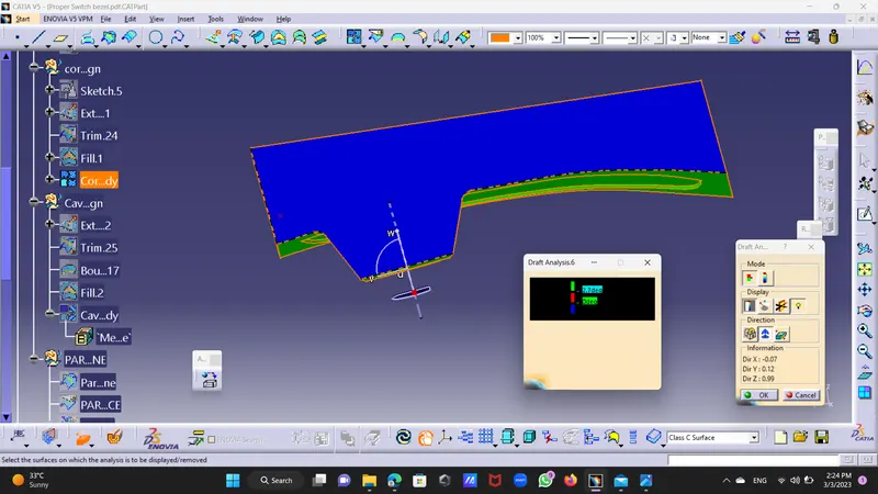
Draft Analysis of Switch Bezel:For Both The Plastic Component.
select compass and put it on axis which is taken normal to the base set it properly.
set draft angle at 2.7 deg .
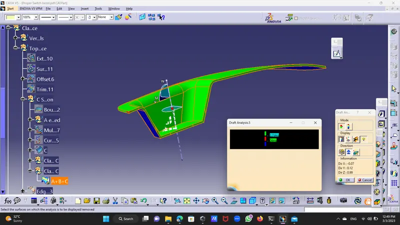
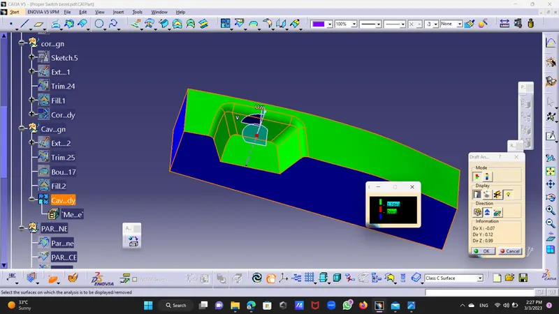
Did draft Analysis of switch bezel at 2.7 deg
green portion shows above 3 deg draft.
red shows draft from 0 to 3 deg.
blure show draft below 0 deg.
3 D View