Week 8 - Challenge 6 - Core & Cavity Design
CORE CAVITY DESIGN
OBJECTIVE:
To create the Core and cavity blocks for the switch bezel component and also do the draft analysis of the component.
CORE CAVITY DESIGN:
The core & cavity are the shaped sections in either half of the mould tool which give the plastic product its final shape. The hot molten material is injected into the core & cavity and then sets hard into shape. The design of the core & cavity is essential in the correct formation of the product. And the following steps are,
STAGE_1: DRAFT ANALYSIS OF SWITCH BEZEL COMPONENT
By using of Feature draft analysis.
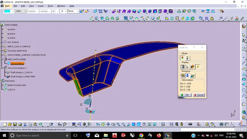
From the above draft analysis with the minimum draft angle of 3 deg. may results my component has divided into core & cavity like the following as,
Blue - As my core block.
Green - As my cavity block.
Because thus the parting line on this area which will not affects(like Flashes) the Class-A surface.
STAGE_2: CORE CAVITY DESIGN
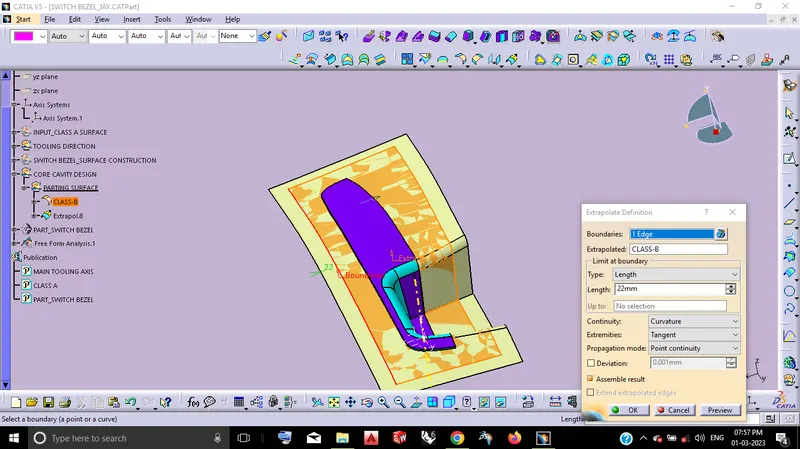
STEP_1: PARTING SURFACE CREATION
From the B-side Class-B final surface make extrapolate to obtain the Parting Surface.
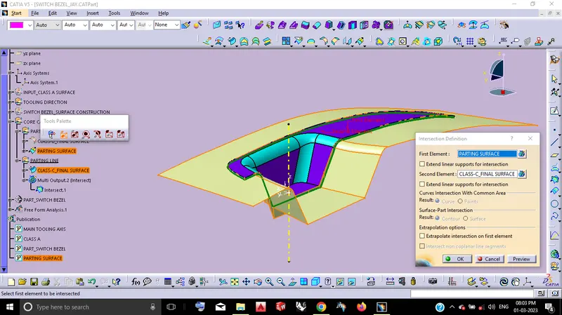
STEP_2: PARTING LINE CREATION
From the Parting Surface by using the Class-C final surface make Intersetion Definition to obtain the parting line.
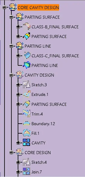
STEP_3: CAVITY DESIGN
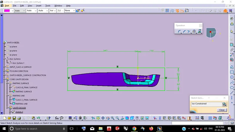
By using og Positioned Sketch defition.
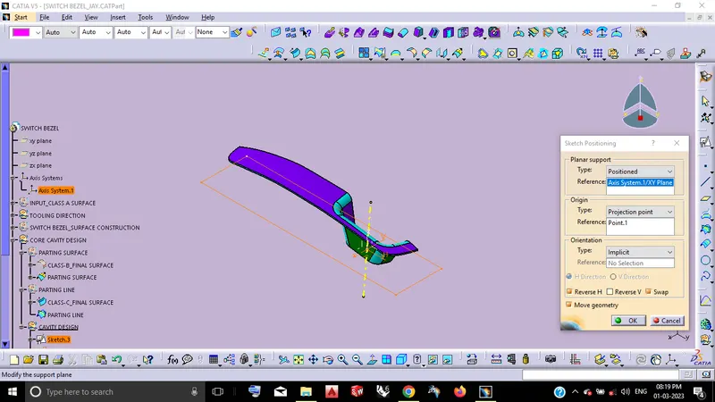
By using of Sketch solving thus the sketch becomes Iso-Constrained.
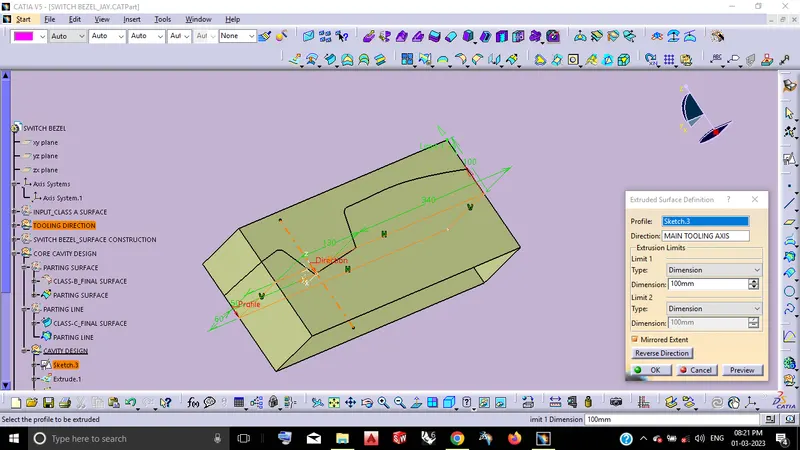
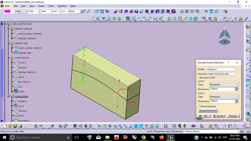
By using of Extrude surface Definititon.
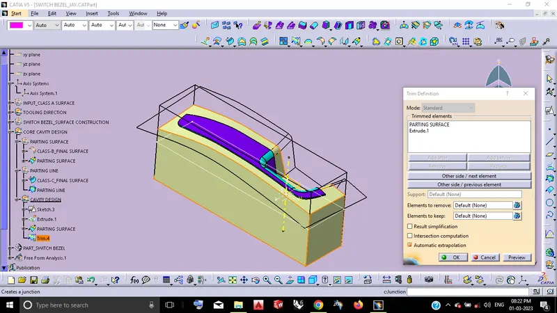
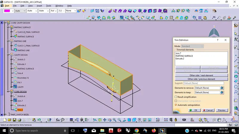
By using of Trim definition.
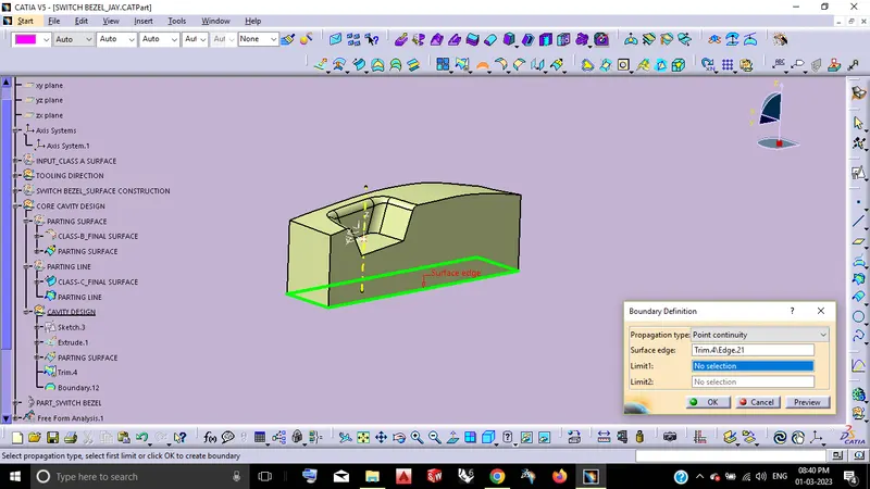
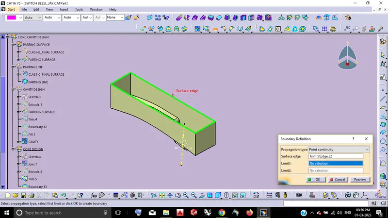
By using of Boundary Definition.
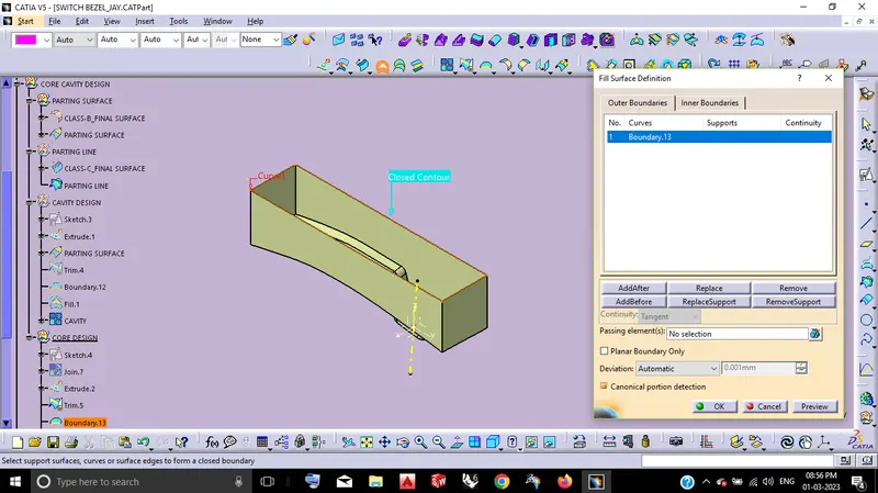
By using of Fill Surface definition.
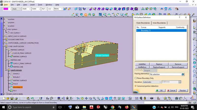
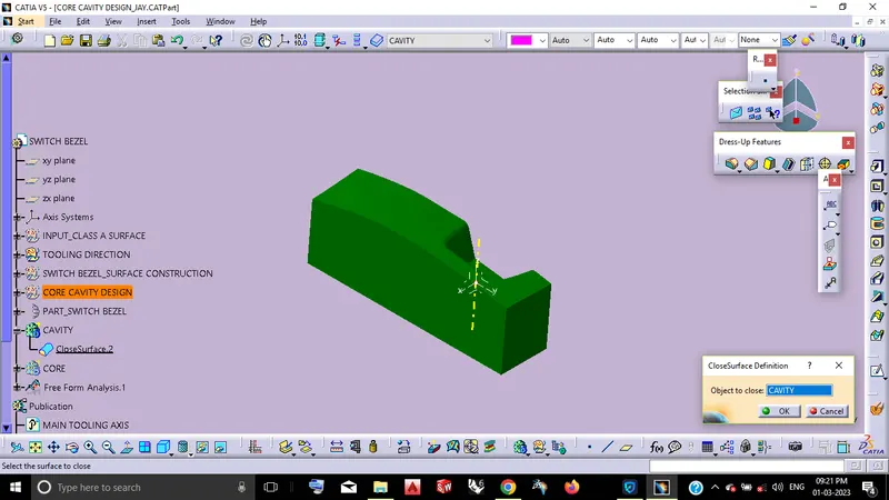
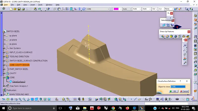
By using of Close surface Definition.
STEP_4: CORE DESIGN
By using of Extrude surface Definition.
By using of Trim definition.
By using of Boundary definition.
By using of Fill surface definition.
By using of Close surface definition.
VIEW ORIENTATION:
EXPLODE VIEW
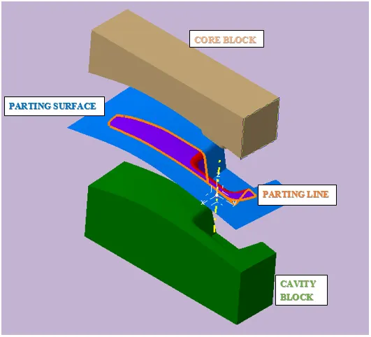
ISO VIEW
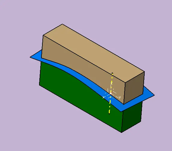
SECTION VIEW
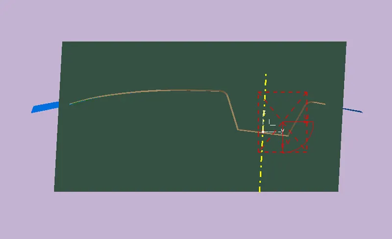
TREE STRUCTURE:
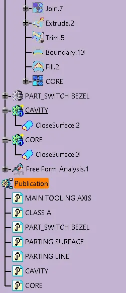
CONCLUSION:
Thus the Core Cavity Design of the Switch Bezel Component has completed by using CATIA V5.
Draft analysis of the component completed.
Parting Line & Parting Surface also completed.