Week 8 - Challenge 6 - Core & Cavity Design
AIM
To create the Core and cavity blocks for the switch bezel plastic component.
REPORT
1. Creation of Tooling Axis
- At first we identify the proper location for the tooling axis to pass through. In this model we find the base of the switch besel to be the ideal surface for tooling axis.
- So using 'multiple extract' we first extract this surface.
- Then we create a point on centre of this surface using point option.
- With this point we create an axis system.
- Looking at the model we identify that tooling can be done through both y and z axis.
- So we first take the yz plane as the reference and using sketch we create a dummy tooling line with respect to the two side walls
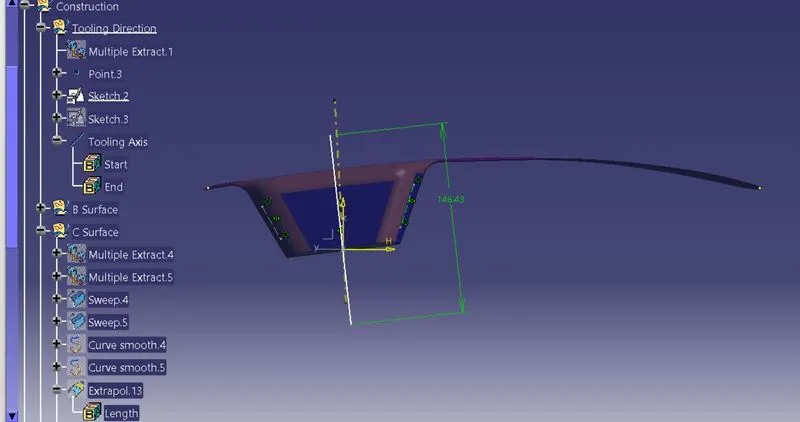
- Then using the zx plane we create another dummy tooling axis.
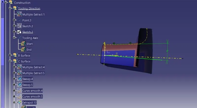
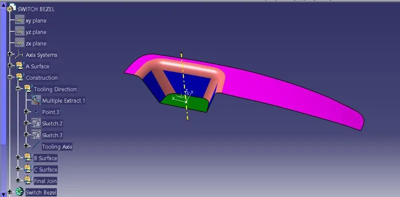
- Using the bisecting lines option we bisect both these dummy tooling axis to form the required tooling axis.
2. Draft analysis on Class A and Plastic component
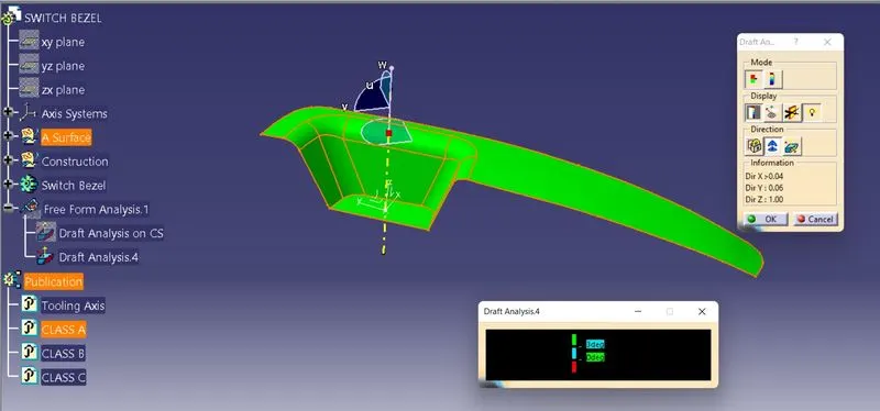
- We select the draft analysis option and analyse it on class A
- From the analysis, it shows that the class A is having a draft angle more than 3 degrees which is as per required.
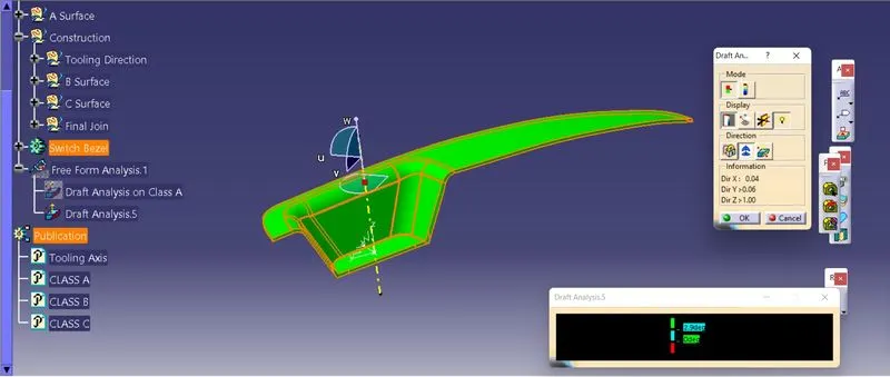
- The draft analysis of the plastic component on this shows that it is at an draft angle greater than 2.9 degrees.
3. Core Design
- First extrapolate class A surface using point continuity.
- Then trim this surface with Class C surface.
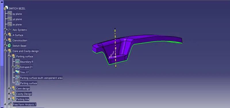
- Now trim the B surface with with the above trim to get the current parting surface with components area.
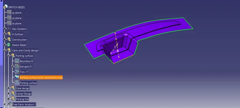
- Draw a rectangular sketch over this.
- Then extrude that sketch with respect to the tooling axis.
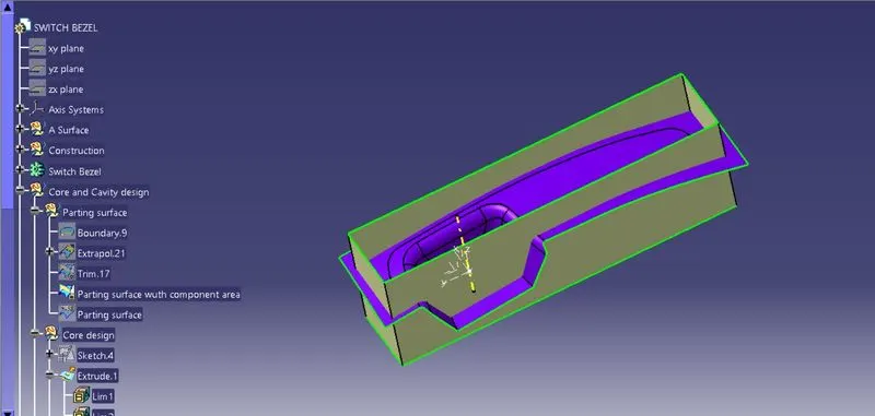
- Trim this extrude with the parting surface and fill up the open portion using boundary and fill option and join them to get the Core design.
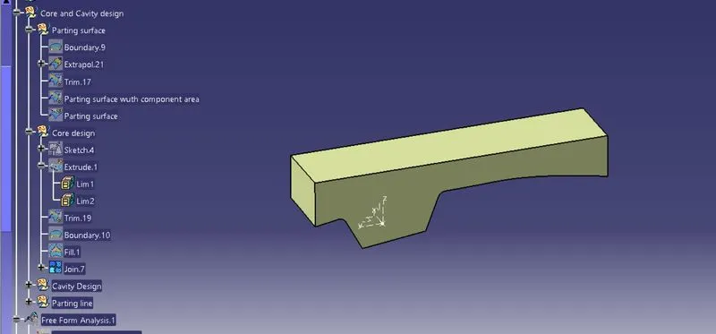
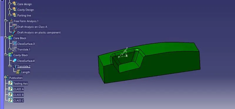
- Go to part design and click on closed surface and click on the design to form the final core component.
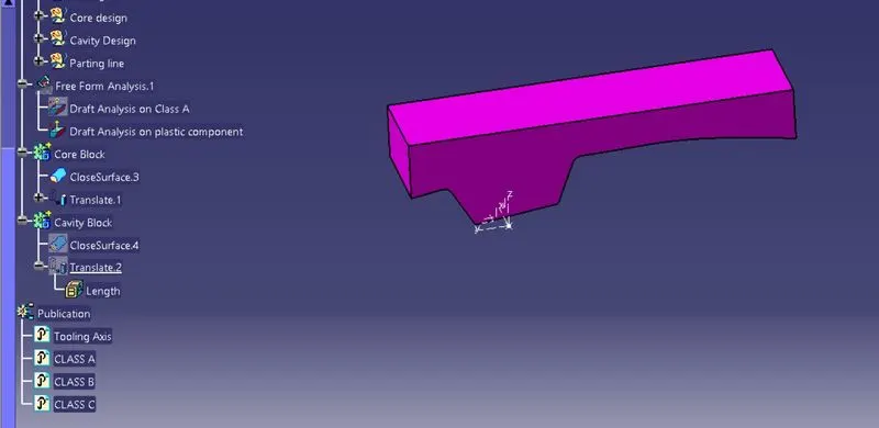
4. Cavity Design
- Cavity is designed by taking the same extruded surface and trimming it with the extruded B surface.
- Here to we use boundary and fill option to close the gap and then join them to form the cavity design.
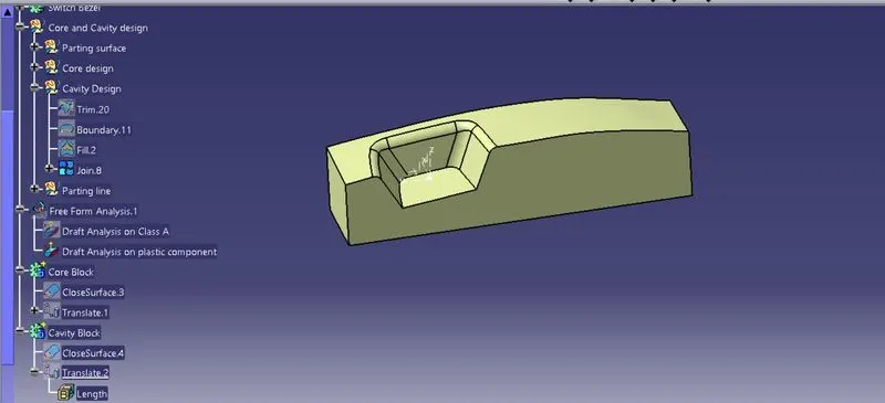
- Go to part design and click on closed surface and click on the design to form the final cavity component.
5. Parting line
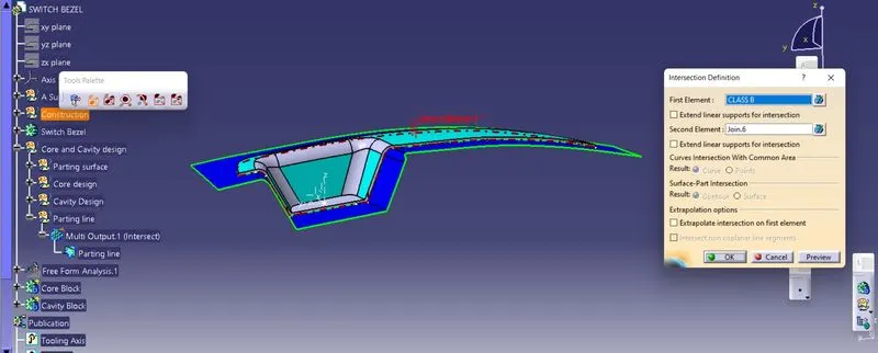
- Use intersection option and intersect between Class B and the join between class A and C to create the partting line which is where the two halves of the mold meet.
6. Core and cavity design
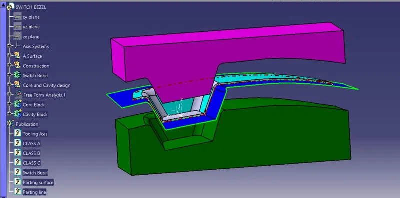
RESULT
1. ISOMETRIC VIEW
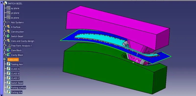
2. FRONT VIEW
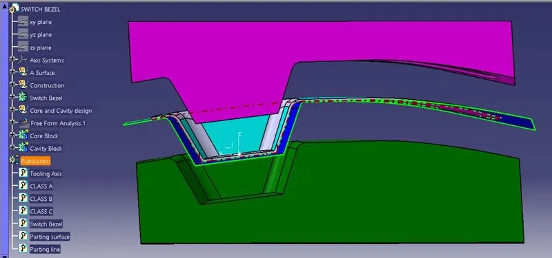
3. SIDE VIEW
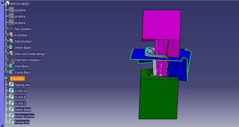
4. TOP VIEW
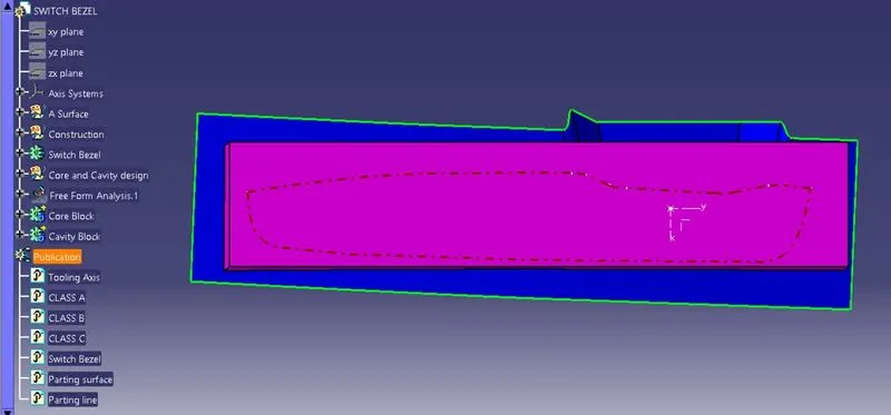
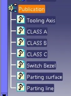
PUBLICATION