Week 8 - Challenge 6 - Core & Cavity Design
OBJECTIVE:
- To design the switch bezel from the given styling surface.
- Create the A-surface and tooling direction for the A-surface.
- Perform draft analysis on the A-surface.
- Create the B-surface and C-surface.
- Create the Core and Cavity for the Switch Bezel.
SOFTWARE USED: CATIA V5
DESIGN METHODOLOGY
Given: A-surface
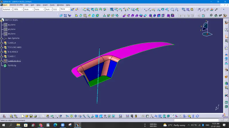
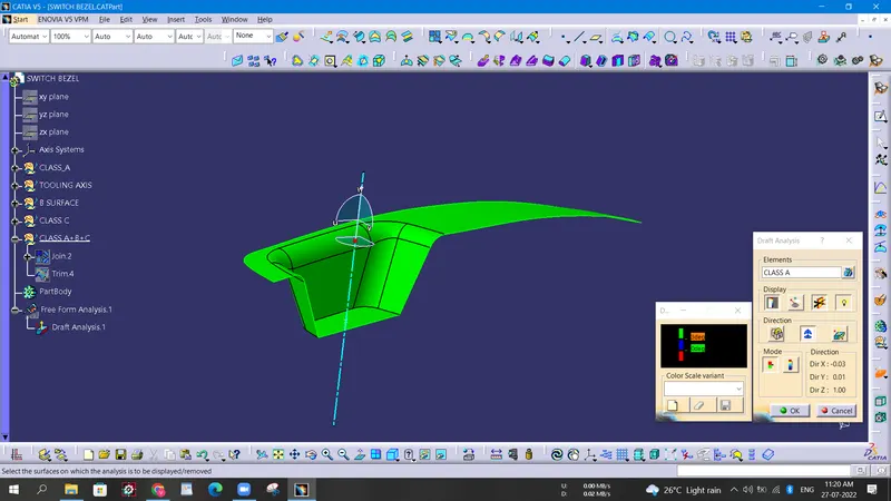
- First, we need to check the given A-surface for any surface errors like open boundaries or twisted surfaces. We can use the boundary command to check for any open boundaries.
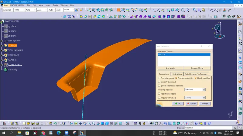
- TOOLING DIRECTION: Tooling direction is the direction in which the core moves away. It is necessary to find the tooling direction of the A-surface as the B and C surfaces will be created according to the tooling direction.
To find the tooling direction we need to clear the inner walls of the Bezel for 3 degrees. Draft analysis is needed to check the angles of the inner walls.
- B-surface creation: For the B-surface, we create an extrapolated surface which will be cut using the C-surface.
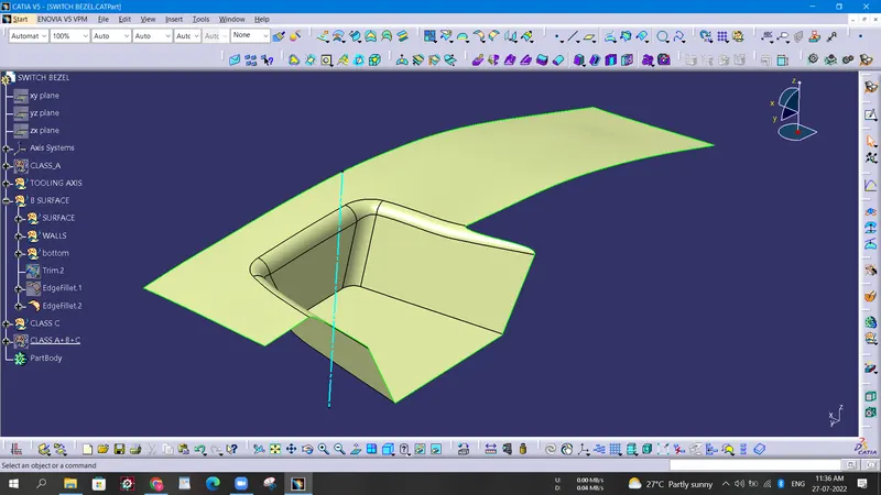
- C-surface creation:
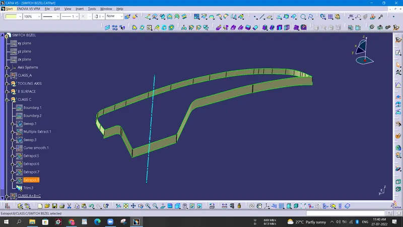
- Draft analysis on the closed body: Draft analysis on the body is performed to check the draft on the A-surface, B-surface, and C-surface. Here the Closing surface follows the draft of the A-surface.
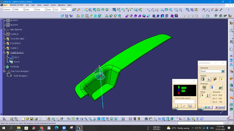
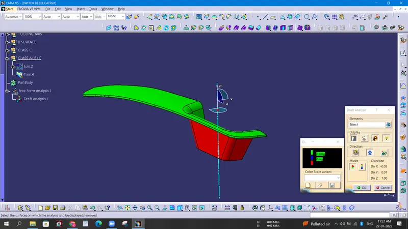
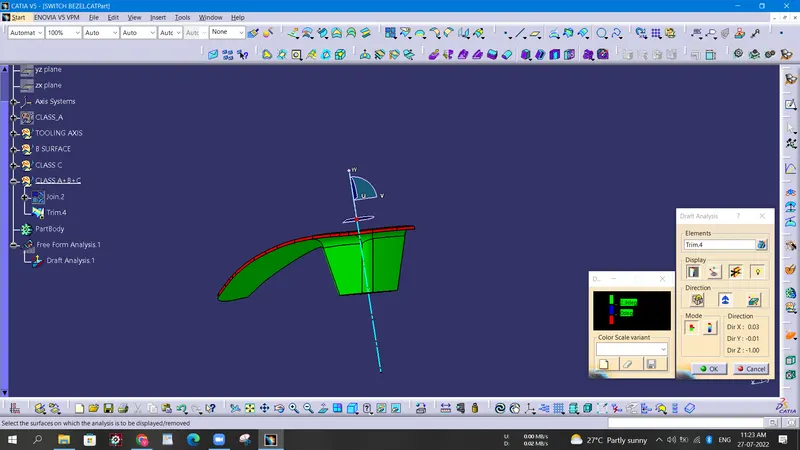
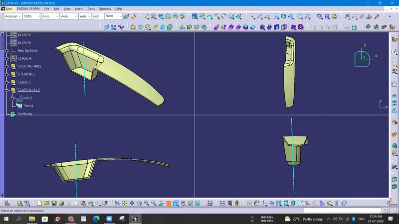
Creation Of Parting Surface
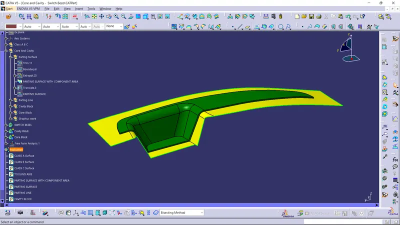
- Class B and Class C surfaces are trimmed and is joined with extrapolated class A surface to obtain a parting surface with component area.
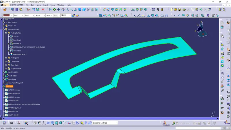
- If the obtained surface is splitted using the parting line, parting surface is obtained.
Parting surface with component area:
Parting surface:
Creation Of Cavity Block
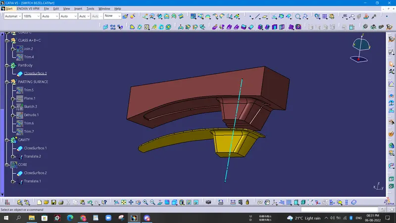
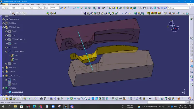
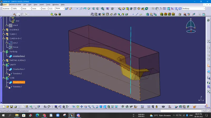
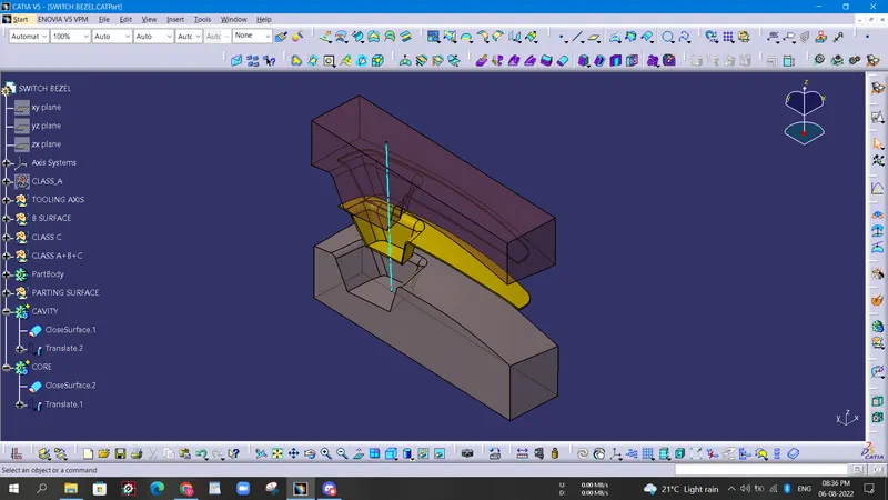
- Cavity block created by initially drawing a rectangle which is to be extruded so as to make it able to trim with parting surface with component area. Thus, a box is obtained which is the cavity block.
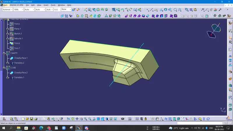
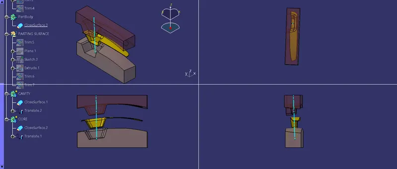
Screenshots Of The Cavity Block In Various Orientations:
Creation Of Core Block
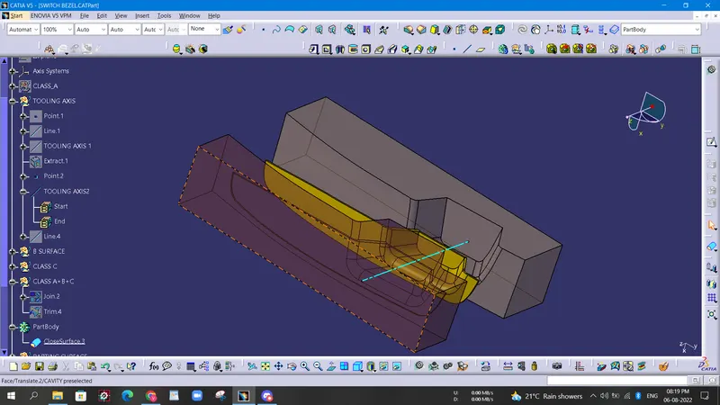
- Core block is obtained by trimming class B surface with the previously extruded surface. Thus, obtained below block is the core block.
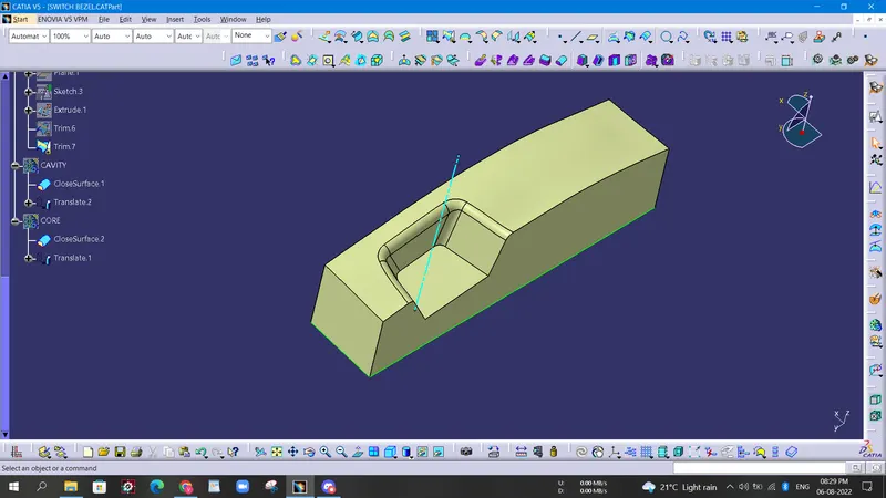
Screenshots Of The Core Block In Various Orientations
CONCLUSION
- Created Tooling axis.
- Created Class B and Class C surface from provided Class A surface.
- Created solid part out of surface modelling.
- Draft analysis of Class A surface and final part is also done.
- Created parting surface for the part.
- Created core and cavity for the solid model.