Week 8 - Challenge 6 - Core & Cavity Design
AIM: Creation of Core and cavity blocks for the switch bezel
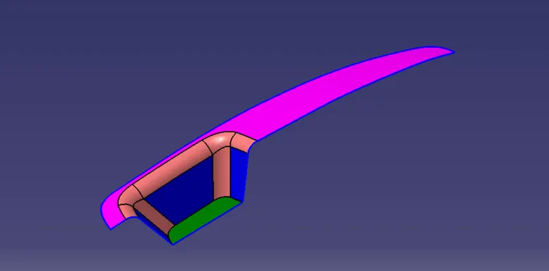
STEP 1: Download the STP file that is provided in the question which is a CLASS A SURFACE for us.
Class A surface is an outer styling surface on which the design engineer starts designing components.
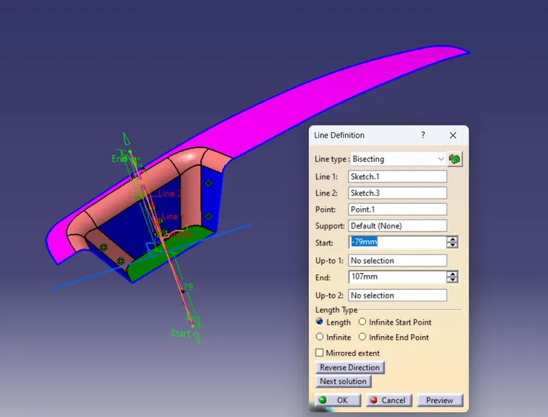
STEP 2: Creation of TOOLING AXIS using the bisecting method-
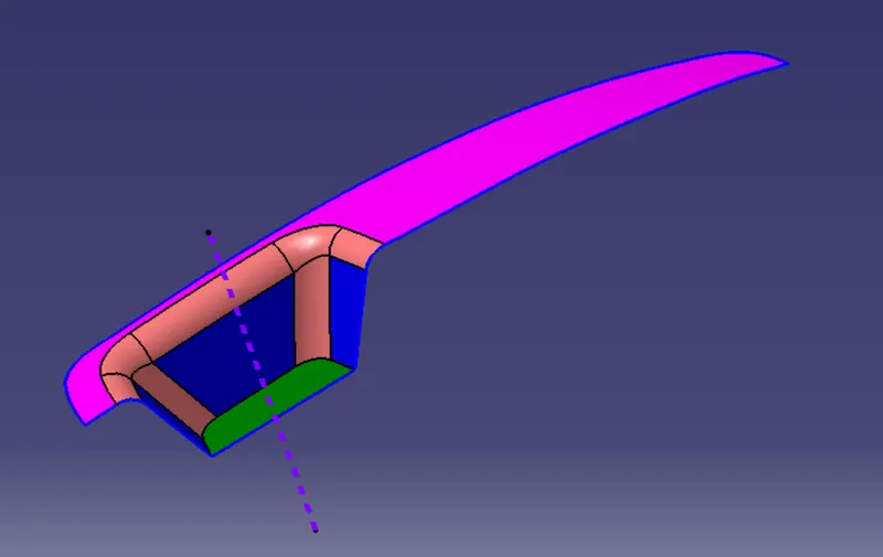
TOOLING AXIS: The direction in which the core and cavity open and close is known as the tooling axis. The draft angle in relation to the tooling axis is given. We must choose the tooling direction before making a mould component from a Class-A surface. Visual inspection, judging complicated surfaces, and the bisecting approach can all be used to make a decision.
PROCEDURE FOR CREATING A TOOLING AXIS USING BISECTING METHOD:
- On the bottom surface, a reference point is made. At that moment, an axis system is developed.
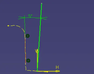
- By employing an intersection with a plane, two alternative cross-section profiles are created.
- Lines are drawn on the boundary intersection profile in question for the first profile in the yz plane. After that, a line is created to divide these two lines.
- For the second intersection profile in xz plane, there is only one surface. So A line is drawn from the center point at 5 degrees angle with the boundary line.
- The two lines produced earlier using the intersection profile are combined to form a bisecting line. The procedure used to establish the tooling axis is known as the "bisecting method," and this bisecting line is referred to as the "tooling axis line."
STEP 3: Creation of class B surface
Offsetting the Class A surface yields this surface. The offset value is the same as the component's thickness. All engineering features are available on this surface.
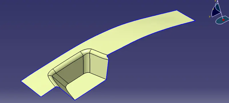
STEP 4: Creation Class C Surface
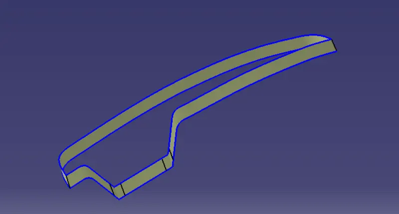
STEP 5: FINAL JOIN AND TRIM
JOIN A & C SURFACE
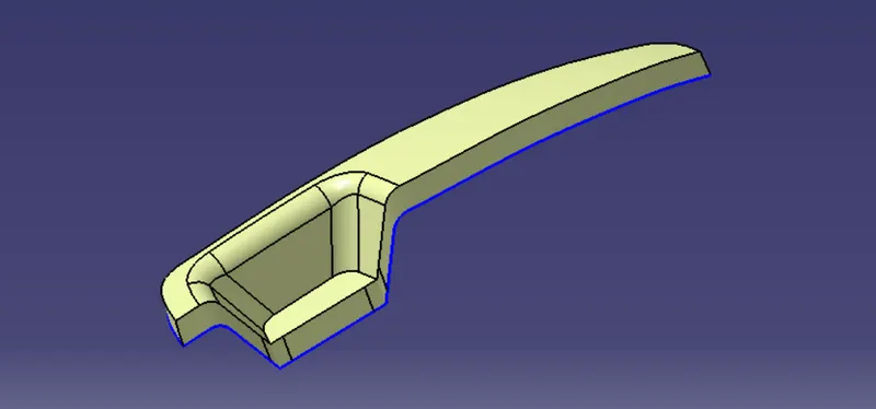
FINAL TRIM BETWEEN JOIN A & C SURFACE AND B SURFACE
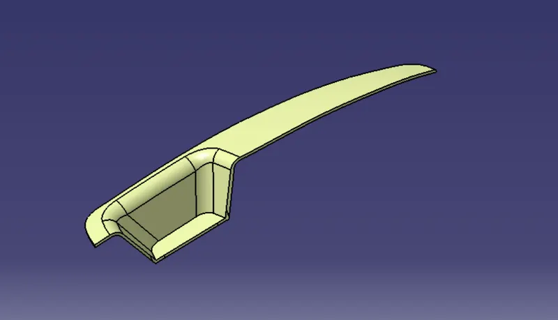
STEP 6: Use the Close Surface feature to make a solid body from the surface
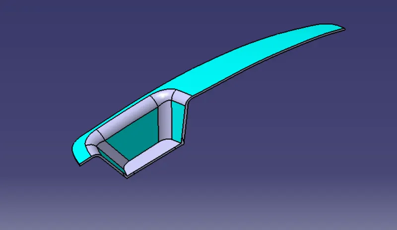
STEP 7: CREATION OF CORE AND CAVITY BLOCK
- The parting surface is created from the intersection of the Class c and class B surface or from where draft angle changes.
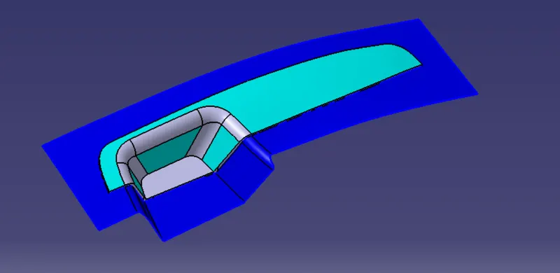
- Next, create a closed surface for a Core block and turn it into a solid body. Both bricks are extruded in the direction of the tool.
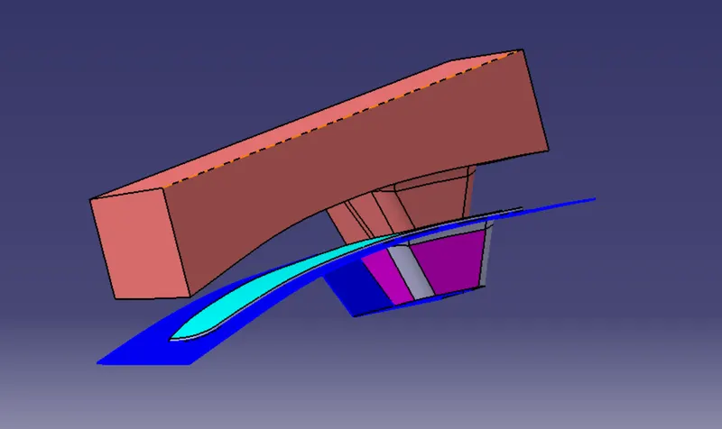
- Create a Cavity block closed surface and convert it to solid body
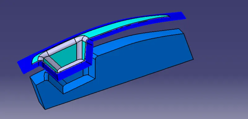
- The following step is to draw a PARTING line from where Class B and Class C & A intersect.
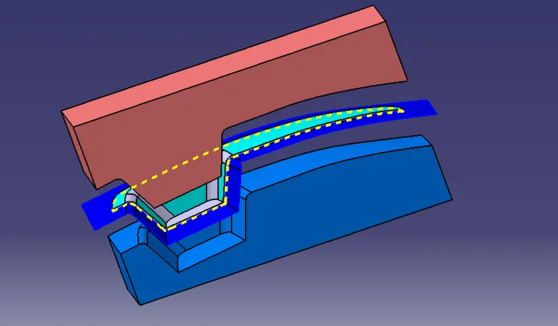
Screenshots of the Draft analysis report for both the switch bezel plastic component:
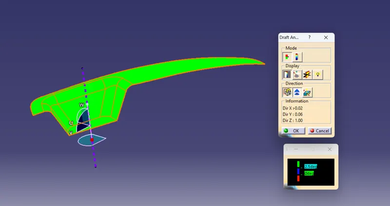
DRAFT ANALYSIS: A draft angle is provided to walls that are parallel to the tooling direction to lessen the risk of damage to components and tools during mold ejection. It aids in taking the part out of the mold.
In Catia, the Draft analysis feature command is utilised to perform Draft analysis. First tooling Direction made that decision. then confirm that material view mode is on. Drag the compass along the tooling axis to align it with the window after it has been opened. Then click on the area of the body or surface where you need to undertake a draft analysis. Give the smallest draught angle in the bottom black colour window, and then match the body colour to this colour scale. Green meant that the draught angle exceeded the minimum. If it is blue, the draught angle is between 0 and the minimum. Red indicates a value less than zero. In this way, we can identify the areas with a draft angle less than the minimum draft angle and work on that area by changing the tooling axis angle.
- Draft Analysis of Class A surface:
- Draft analysis of final closed surface area:
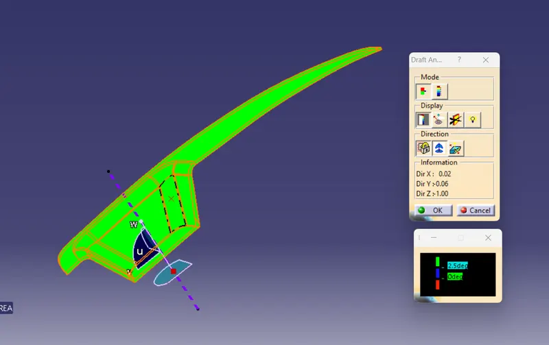
Both the draft analysis is clearing for 2.5 degree.
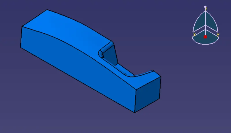
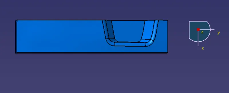
Screenshots of the core and cavity blocks in various orientations (Isometric, Front, Side, and Top View)
- CORE BLOCK SCREENSHOTS:
- Isometric view
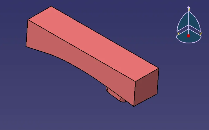
- Front View
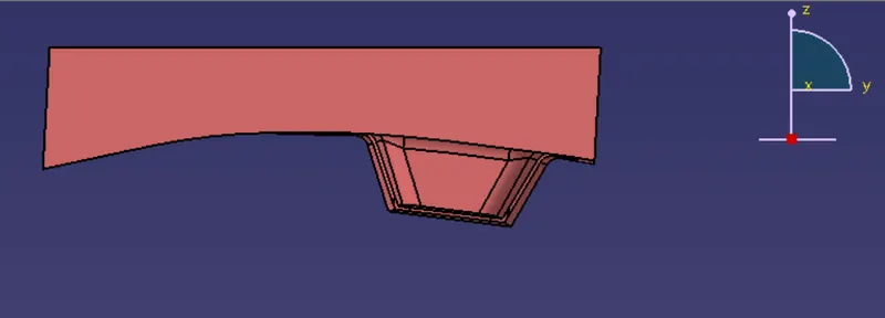
- Side View
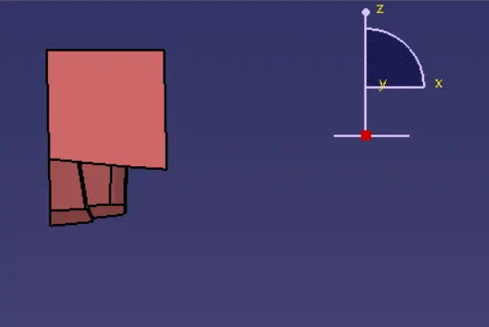
- Top View
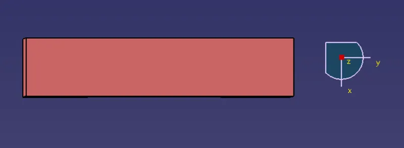
- CAVITY BLOCK SCREENSHOTS:
- Isometric view
- Front View
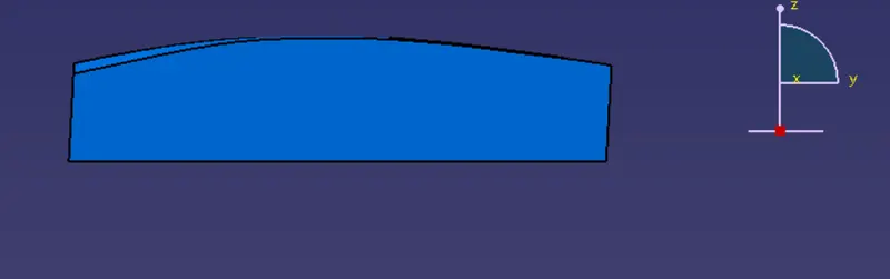
- Side View
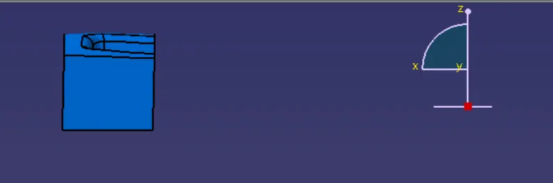
- Top View
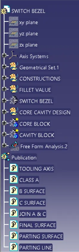
TREE STRUCTURE:
CONCLUSION:
Plastic component In CATIA V5, Switch Bezel is produced from a given Class A surface. The Tooling Axis designed for the Class A surface satisfies the draFt angle requirement. Additionally, solid plastic component draFt analysis is done. Successful creation of the Mold Core, Cavity Block, Parting Line, and Parting Surface.