Wiring harness design in CATIA V5 - 3D modeling Week 2 Challenge
There are two connectors-
1. Deutsch DT06 – 08SA
2. Tyco 174357-2 with a clip attachment Tyco 85229-1
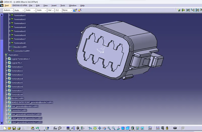
CONNECTOR 1- Without Clip attachment- C-DT06-08SA:
Image 1- Creating Bundle entry point
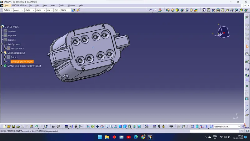
Image 2- Creating Connector Point on Mating Surface and Creating an Axis System with appropriate x,y, and z Direction.
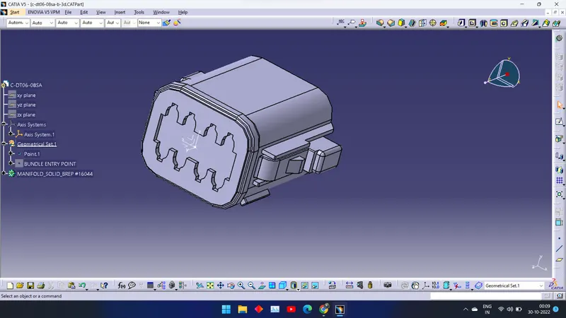
Image 3- Defining part as a Connector
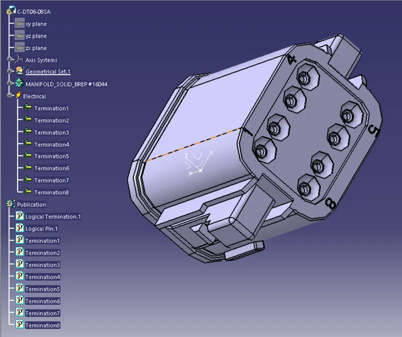
Image 4- Defining Bundle Connection Point
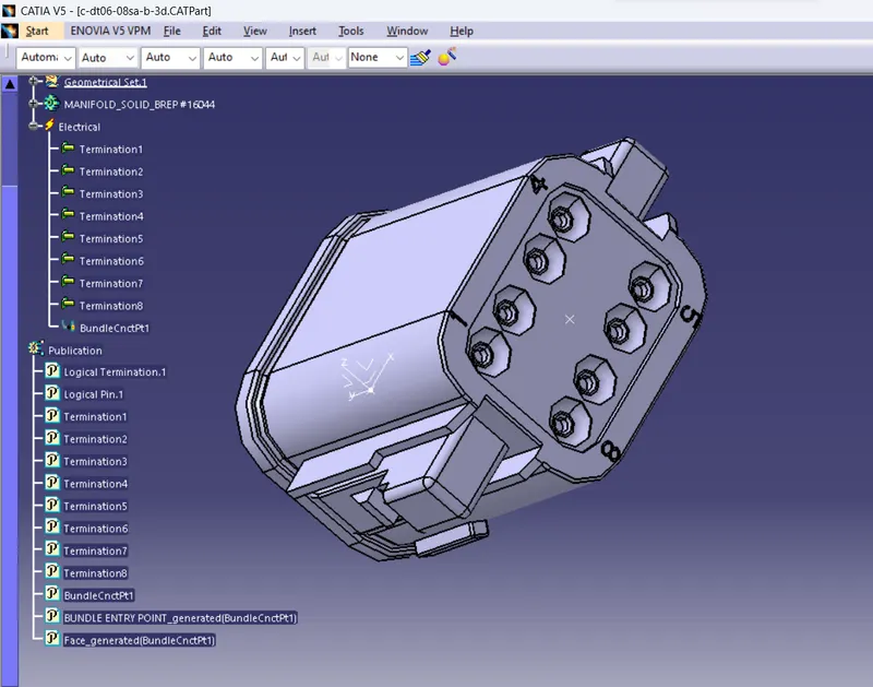
Image 5- Defining Connector Connection Point-
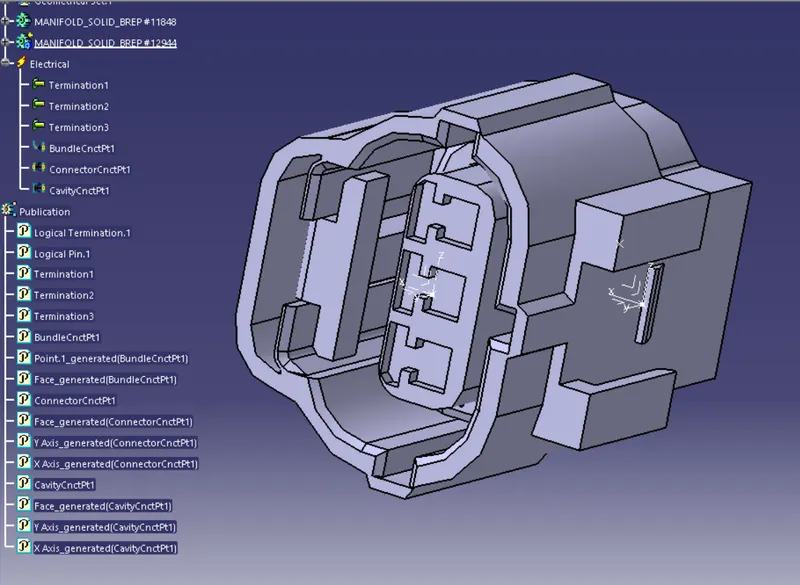
CONNECTOR 2- With Clip attachment- C-2-174357-2-E-3D :
Image 1- Creating Bundle point and mating point along with axis system also for clip attachement:
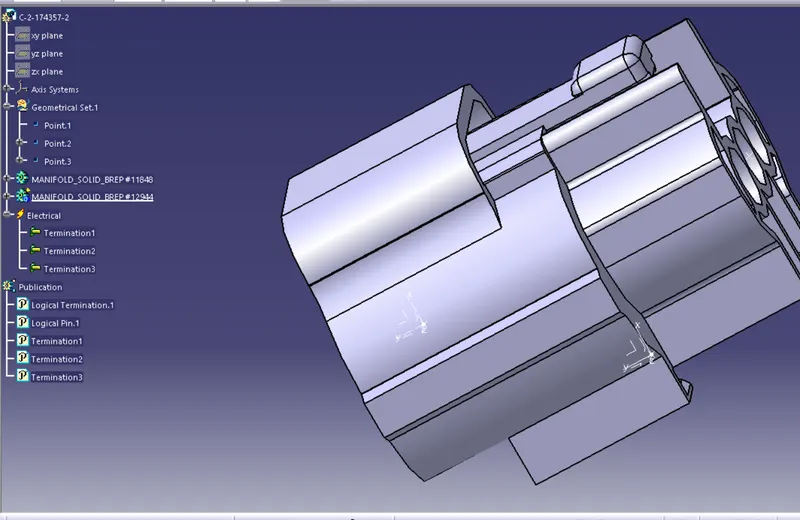
Image 2- Defining part as a connector
Image 3-Defining Bundle Connection Point-
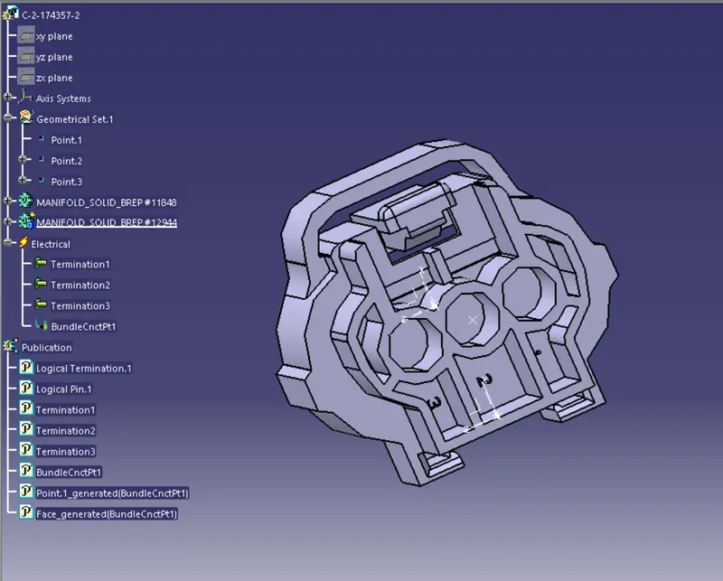
Image 4- Defining Connector Connecting Point-
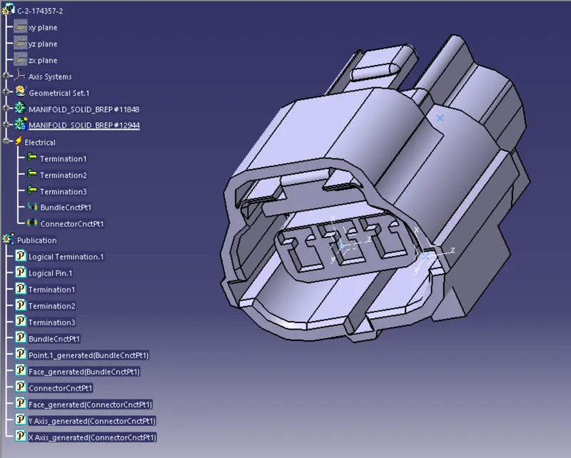
Image 5-Defining Cavity Connection Point-
CLIP 2- C-0085229-01-A-3D:
Image 1- Defining the Geometrical Parameters of the part-
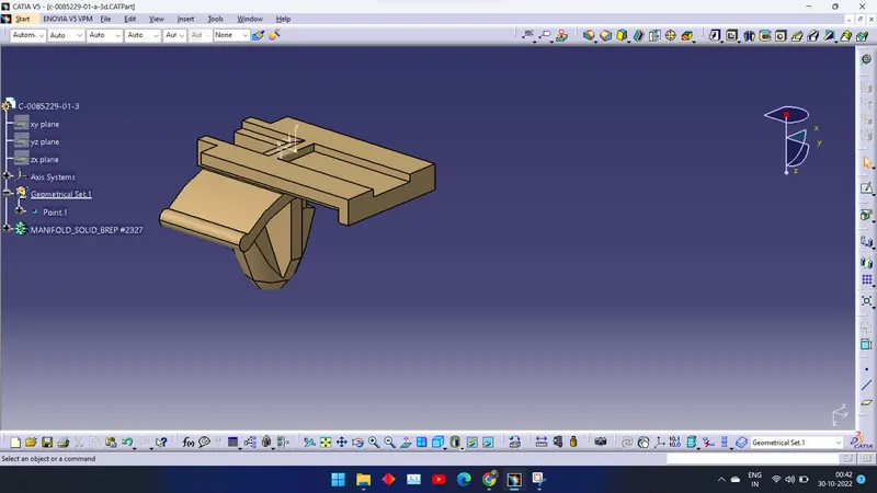
Image 2- Defining mounting equipment and then a cavity :
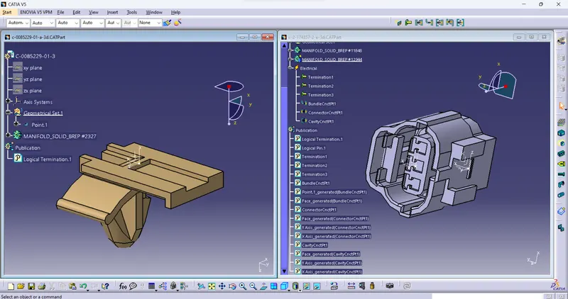
CLIP AND CONNECTOR ELECTRICAL ASSEMBLY-
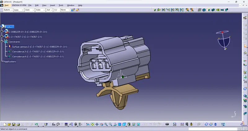
Conclusion- The connectors and the clip were both classified as electrical mounting equipment and electrical connectors, respectively. The components were provided with all essential electrical and geometrical qualities.