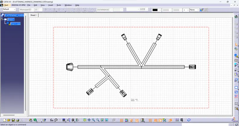
Wiring harness design in CATIA V5 - 3D modeling Week 7 Challenge
STEP 1: CREATING ROUTED HARNESS ASSEMBLY FOR WHICH FLATTENED-VIEW HAS TO BE CREATED
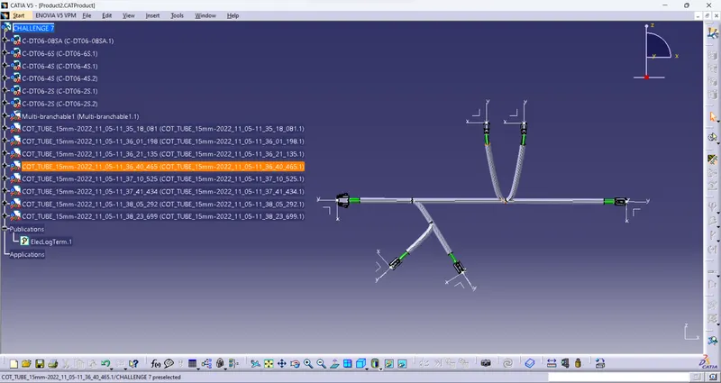
The Electrical Harness Flattening workbench of CATIA V5 should be used to create a flattened view of any wiring harness. We must ensure that the flattening file is located in the same folder as the harness assembly's component elements.
STEP 2- Defining Harness Flattening parameters-
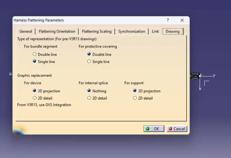
In the Electrical Harness Flattening workbench, we should first create a new product file. By clicking on its icon as displayed above, we should define the harness flattening settings next. We should select the parameters as indicated above in the general tab. We should define the parameters for the drawing tab as shown below once the general tab settings are finished.
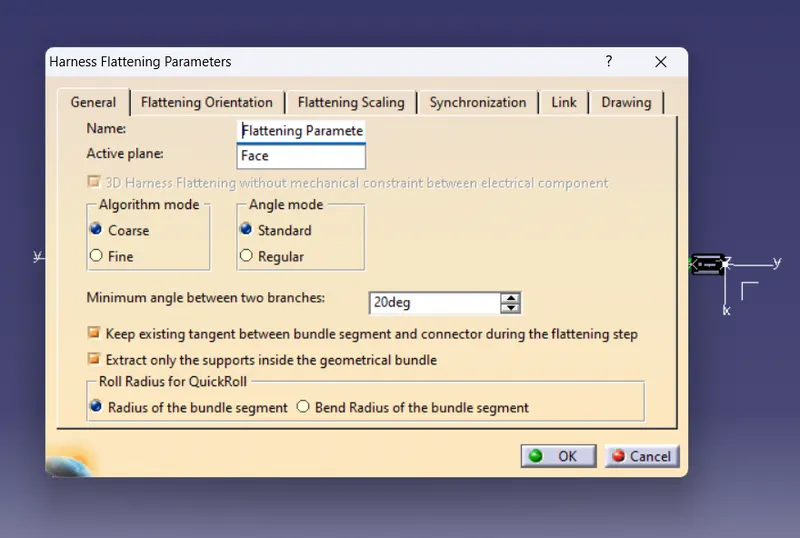
It should be noted that the protective covering and bundle segment have different ways of representation. In the event that the connectors are included in the electrical drawing catalogue, "3D projection" can be used for devices as well.
STEP 3 -Utilizing the "Extract" feature, insert the harness assembly into the freshly produced Flattening Product.
The Flattening Product and Harness Bundle tabs should be vertically aligned first. Now, as illustrated below, we should incorporate the harness assembly into the flattening product using the "EXTRACT" feature of the electrical harness flattening workbench.
It should be noted that the "EHF" file, which stands for "Electrical Harness Flattening," has replaced our geometrical bundle assembly or harness assembly file.
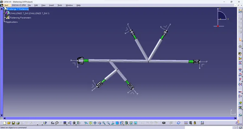
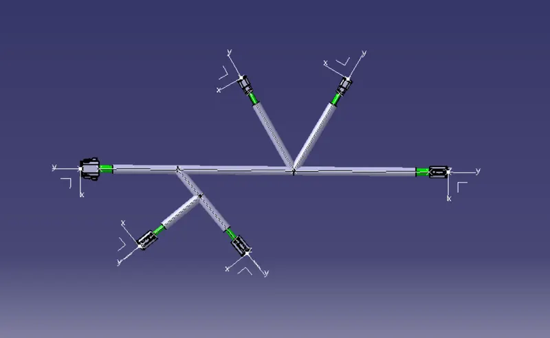
STEP 4 - Flattening of the harness and Rotate the bundle segments.
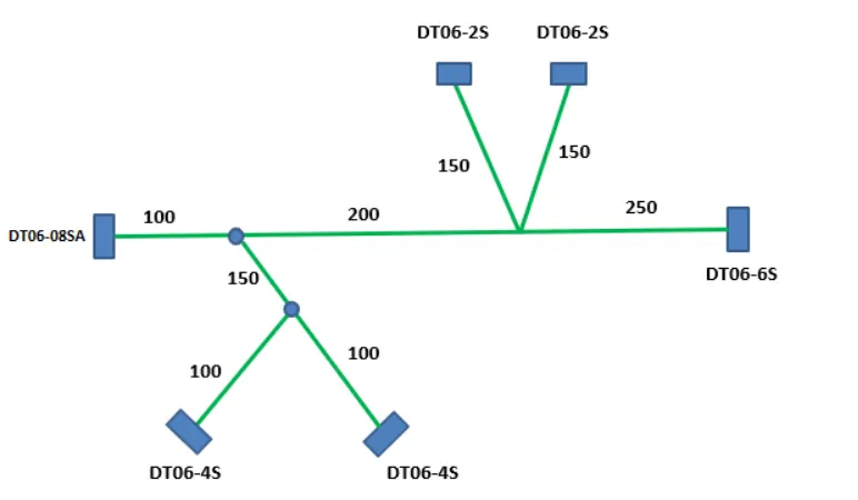
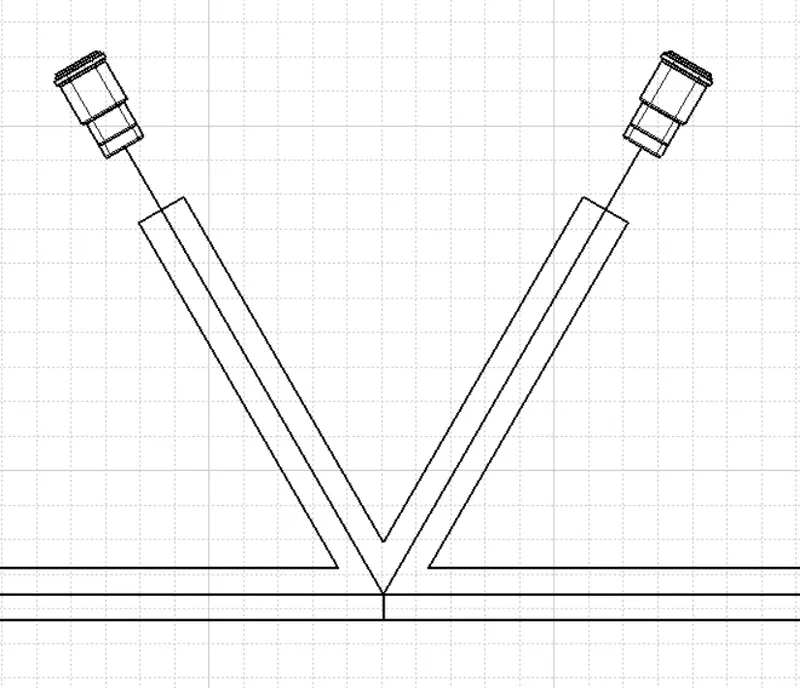
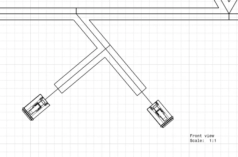
STEP 5 - Flattening Drawing Creation