Wiring harness design in CATIA V5 - 3D modeling Week 5 & 6 Challenge
STEP 1:
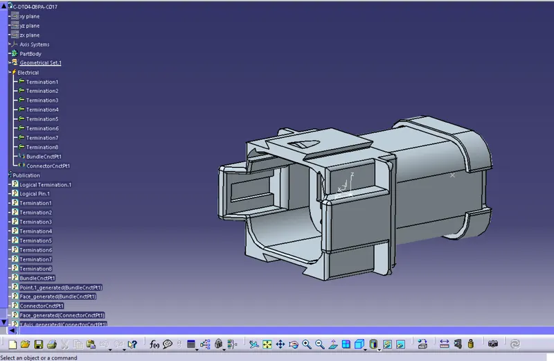
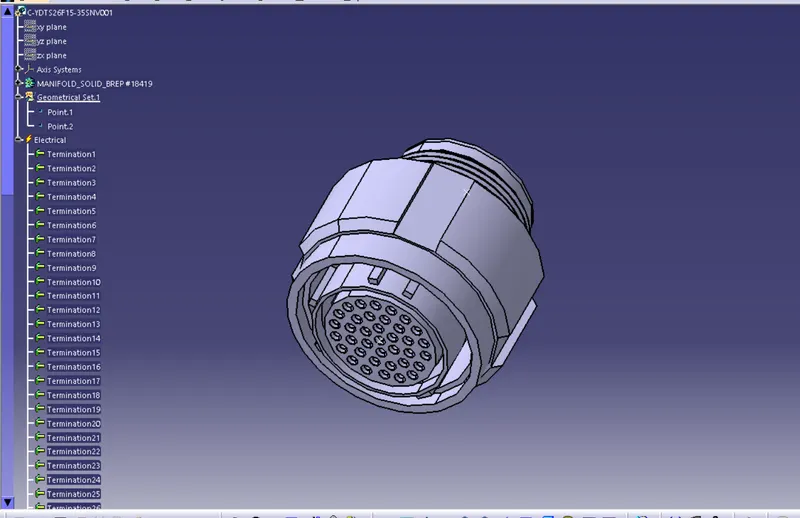
Create geometric and electrical definitions for all electrical connectors that will be used in the wiring harness.
Connectors Used in Harness A
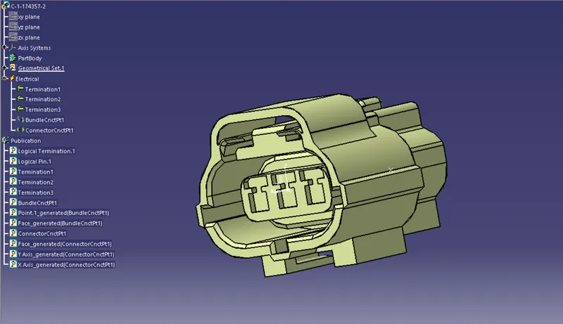
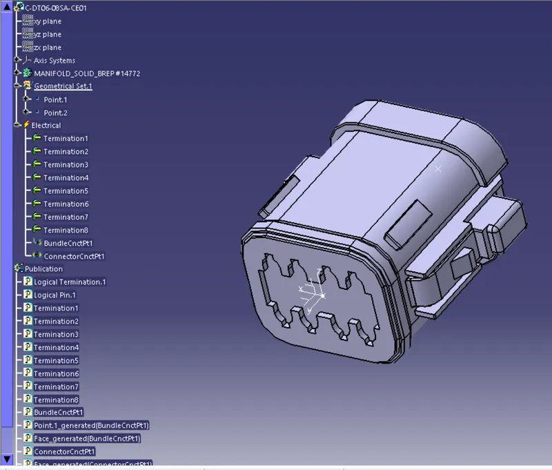
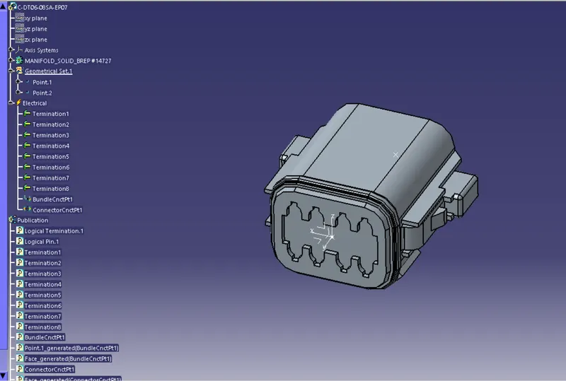
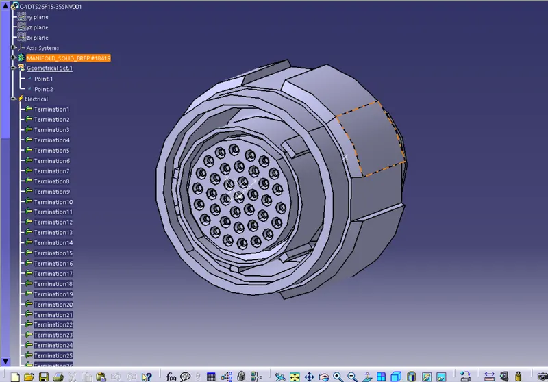
Connectors Used in Harness B-
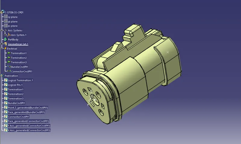
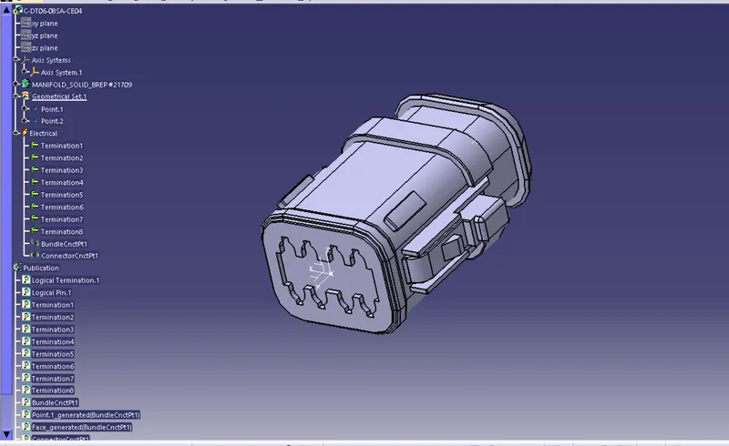
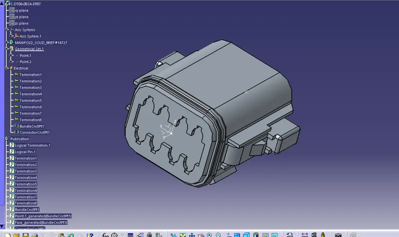
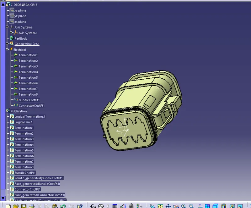
STEP 2:
Create harness A and harness B as illustrated below using the CATIA V5 electrical harness workbench.
First, all of the connectors are positioned correctly. Second, between the connectors, bundle segments containing branch points and branches are generated, as illustrated below.
For different bundle segments, bundle diameters of 12mm, and 8mm are presumptive. The bend ratio is 1.4 and the slack is 0% for the entire bundle.
1. HARNESS A
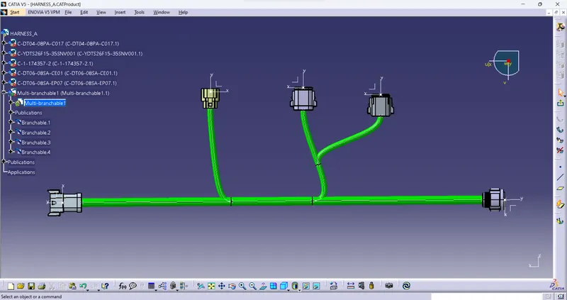
The bundle continuity needs to be examined after harness A created.
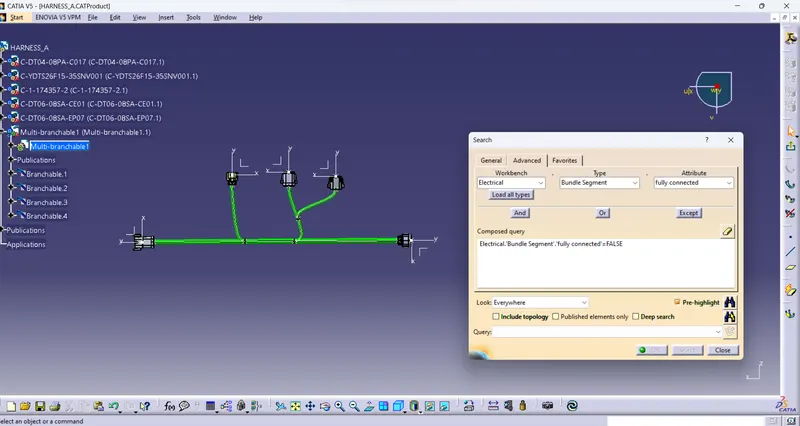
Go to Edit>Search>Advanced>Electrical Workbench>Type-Bundle Segment>Attribute-Fully Connected. Make sure multi-branchable is chosen.
If "TRUE" is chosen, all bundle segments that are connected will be shown; if "FALSE," all bundle segments that are not connected will be shown.
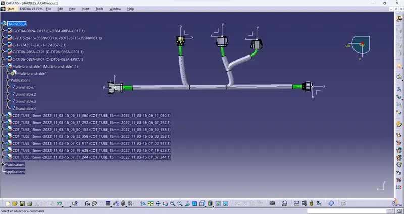
With Safety Corrugated Tubes keeping ends 30mm away from the Connectors
2. HARNESS B
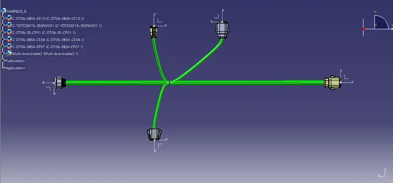
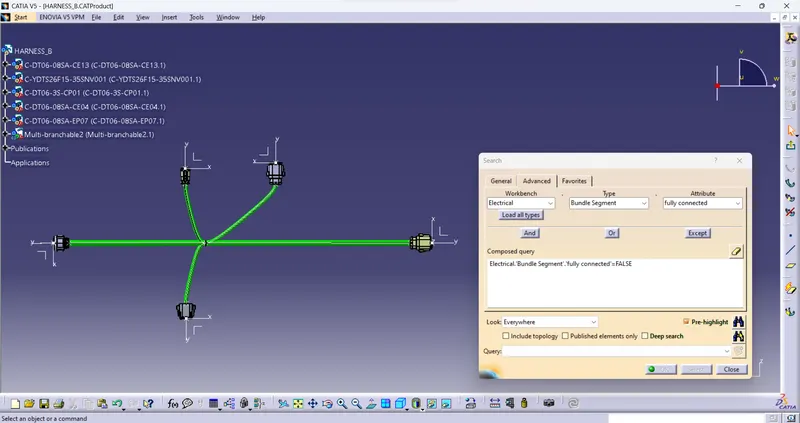
The bundle continuity needs to be examined after harness B is created.
Go to Edit>Search>Advanced>Electrical Workbench>Type-Bundle Segment>Attribute-Fully Connected. Make sure multi-branchable is chosen.
If "TRUE" is chosen, all bundle segments that are connected will be shown; if "FALSE," all bundle segments that are not connected will be shown.
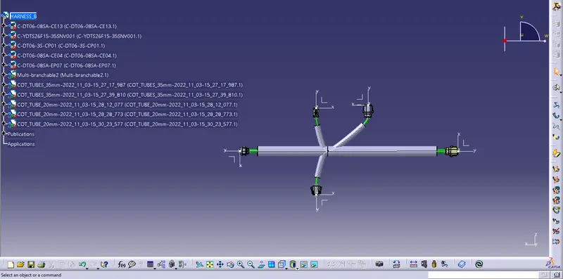
With Safety Corrugated Tubes keeping ends 30mm away from the Connectors
STEP 3:
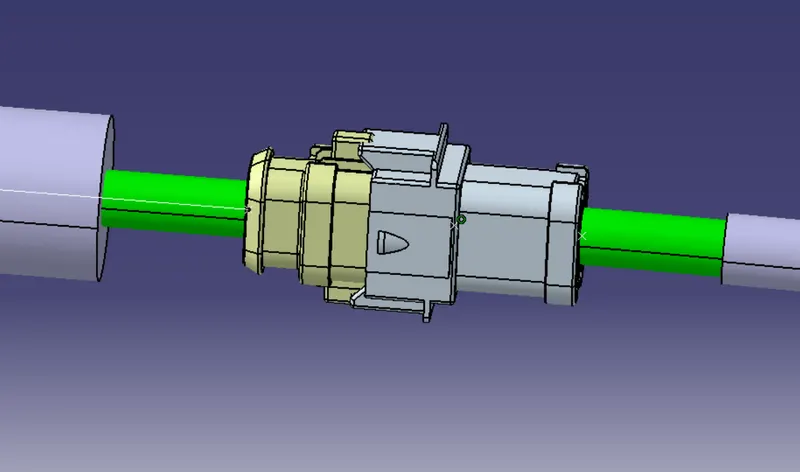
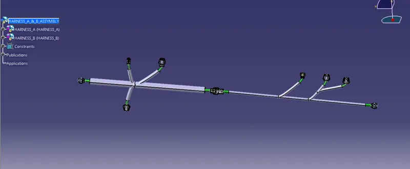
Wiring Harness A and Harness B must be electrically connected in this step. The two harnesses need to be electrically connected, which requires a few procedures.
STEP 4:
In this step, we'll search Harness A and B for bundle warnings.
Geometric bundle alerts are shown for the Bend radius, Bundle diameter, and Vector position. A yellow flash will show up next to the faulty branchable in the tree structure if these inputs or values are wrong. Depending on how the bundle segment is routed, we can either add slack or adjust the segment point's vector location to solve the issue. There isn't an error in our situation.
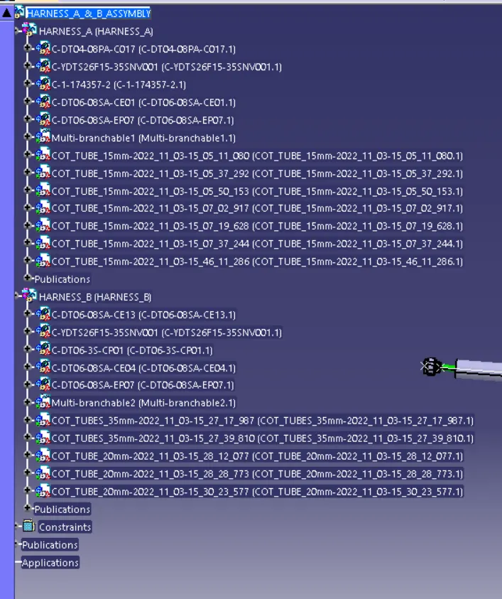
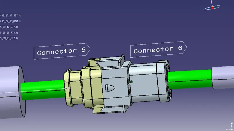
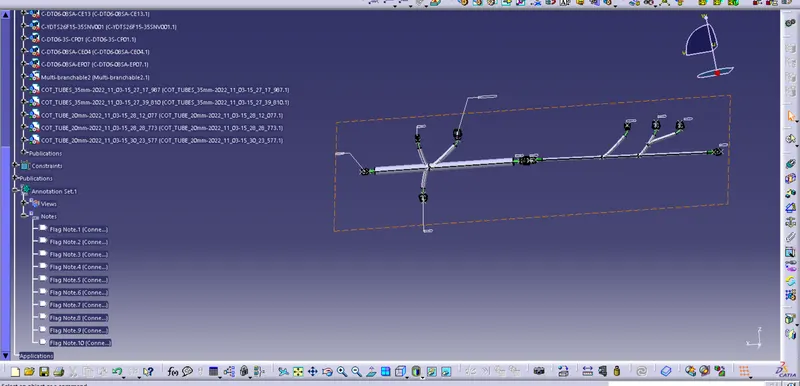
STEP 5: Adding annotation to all connectors:
STEP 7:
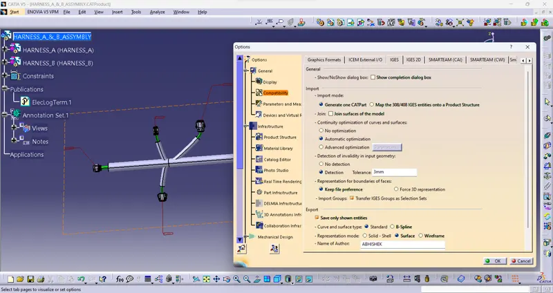
Our Final Harness Assembly file needs to be converted into IGS format before we can move on. The steps listed below must be followed in order to achieve this.
Toolbox for Mechanical Assembly>Catalog Part Generation from Product
The complete product file is turned into a single part when the CAT part has been created. It is now evident that the bundle segments are all grey in colour. To match the Final Harness Assembly, we'll go back and add green colour to each bundle segment.
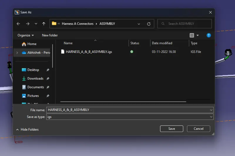
Finally, we may utilise the "SAVE AS" function to save the CAT component file as an IGS file, as demonstrated below.