Week 8 - Challenge 6 - Core & Cavity Design
OBJECTIVE
Create the Core and cavity blocks for the switch bezel design.
REQUIREMENTS:
Software Knowledge about CATIA V5.
PROCEDURE
Open the switch bezel file.
So further creation of core and cavity takes place from the existing of switch bezel file. so let's give some colours to the surfaces to differentiate them.
Tooling axis creation
The tooling axis is the axis and direction in which a sheet of metal is drawn so that the finished component may be removed with ease. When finished, the material must be removed, which depends on the tooling axis.
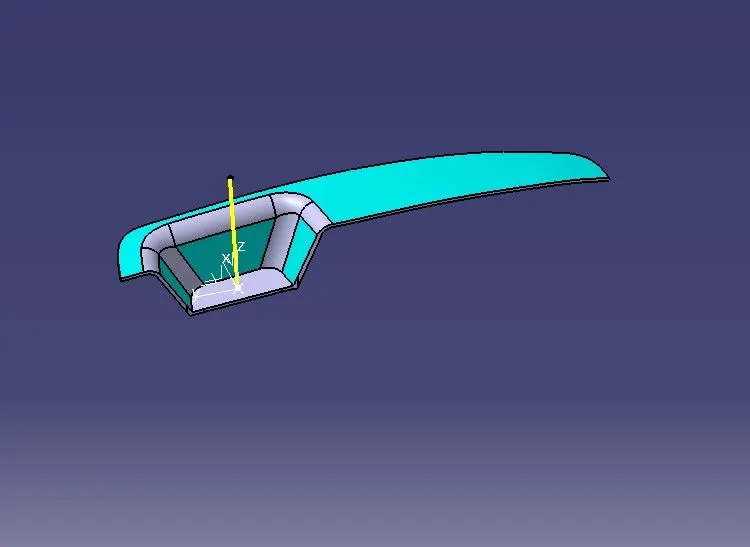
Extract the base surface of the given Class- A Surface and create the center point of the Extracted surface.
Then create two sketches on two planes by taking the cross section of the given surface in the particular plane, tooling axis created from the two lines using the cross section of the surface on y plane as bisecting line.
Tooling axis created from the two lines using the cross section and also creating one with the help of cross section line of the surface on X plane as bisecting line.
And now by creating another bisecting line using those two plane sketches is the tooling axis for this particular Class - A surface.
DRAFT ANALYSIS OF SWITCH BEZEL
To perform draft analysis, click on Insert >>Analysis >> Feature Draft Analysis.
To tackle this issue, CAD engineers uphold a common design rule for plastic moulds or dies, which ensures that there are no issues with ejecting plastic components. Therefore, every plastic component is designed with a minimum of 3 to 10 degrees of draft angle.
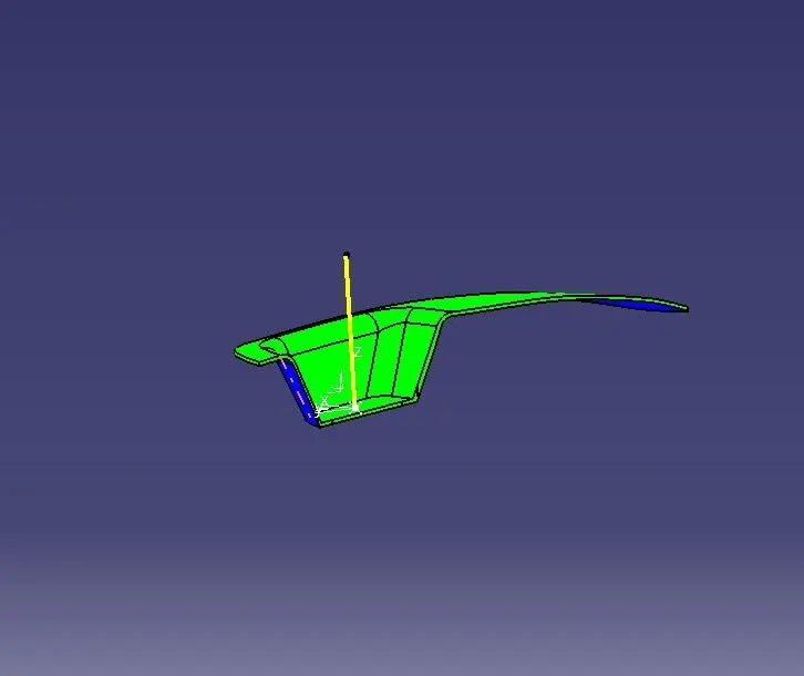
Go to the Direction block in the draf analysis toolbar and select the "Use the compass to set the new current draft direction" option to align and fix the compass to the tooling axis (or just click on the compass symbol). Bring the compass to the surface at this point, align it with the class A surface's tooling axis, and then click the lock icon next to it in the direction block. We can complete the draught analysis process by clicking "ok" on the toolbar for draft analysis.
The Minimum Draft angle 0.5 was given to the final out come and it has passed without any errors.
THE CORE BLOCK
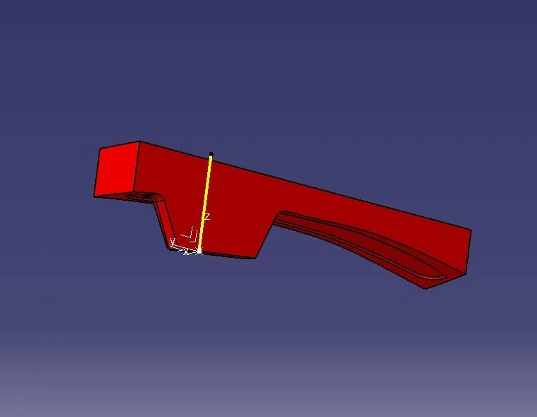
By Class C Surface and A surface triming the interestions.
so now by using Class B Surface sketching a rectangle and making it constrain.
making sure that the rectangle does't come out of the B surface.
now extruding the sketch.
creating boundary on open surface on top end and filling it with surface and joining them using join command and trim the required surfaces.
THE CAVITY BLOCK
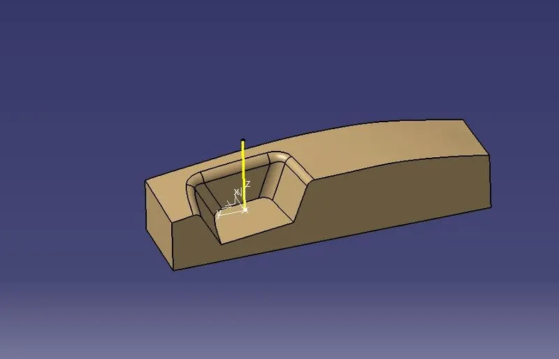
Similar process now B and C surface intersting and trim.
extruding the existing sketch.
This time the bottom part is constructed with a boundary and filling the surface.
again using join command and joining them and making sure that there is no gap between them.
PARTING LINE AND PARTING SURFACE
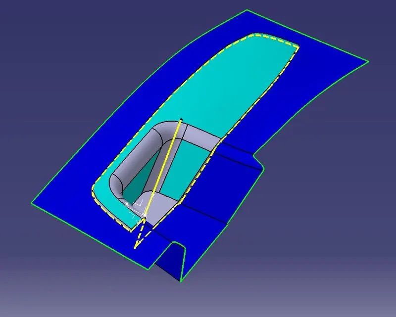
The line in yellow doted line are parting lines i.e the gap between switch bezel and parting surface is called parting line.
the dark blue surface in the below picture around the switch bezel is called parting surface.
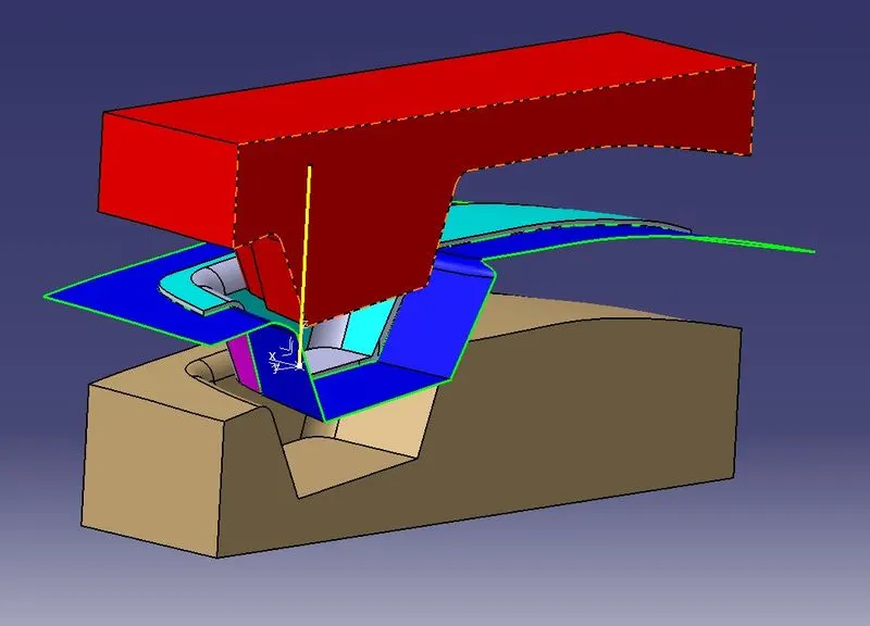
ALL THE PARTS TOGETHER
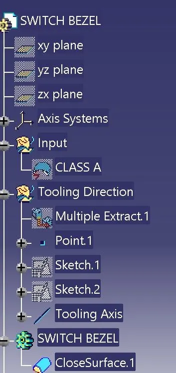
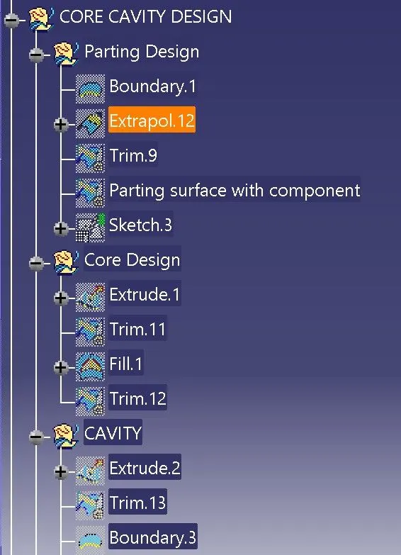
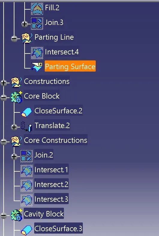
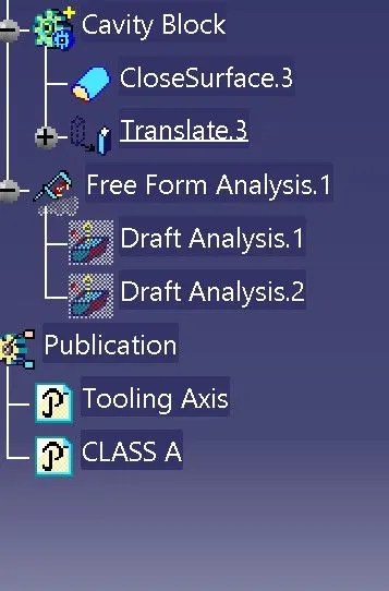
FEATURE TREE FOR MODEL
CONCLUSION
Thus the Switch Bezel Plastic component is completed, the tooling axis is created, meeting the requirements of the draft angle.