Week 8 - Challenge 6 - Core & Cavity Design
DESIGN OF THE CORE & CAVITY FOR SWITCH BEZEL
AIM:
To create the Core & cavity for Switch bezel component.
SOFTWARE USED:
Catia V5
DESIGN PROCEDURE:
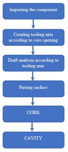
IMPORTANCE OF TOOLING AXIS:
The Tooling Direction is the direction that the mould pulls apart. The mould is built into two separate pieces. You have a Cavity side and you have the Core side. The Core pulls apart from the Cavity and that's the Dyeline or the Tooling Direction. There are different methods to find out the tooling direction. Here we are using bisecting method to find out the tooling direction. We can use any method the ultimate aim is to reduce the cost of manufacturing by reducing the complicity in manufacturing the component.
- It is the direction in which the component will be ejecting after the molding process is completed.
- The direction of tooling axis should clear the maximum portion of the part.
- It should be selected in such way that number of side cores will be minimum as it will add more cost to the process.
IMPORTANCE OF DRAFT ANGLE:
A functional part for injection molding has to have drafts facing both cavity and core sides to reduce the risk of damage to the parts and ensure ejection. As the molten plastic flows into the closed die and fills the cavity, the material shrinks inside the mold upon cooling and as a result grips the core. Draft angles should be at least 3° to facilitate the part ejection.
- Reduces the chance of damage to the part due to friction during release.
- Reduces wear and tear and chances of damage to the mold.
- Ensures a uniform, smooth, unscratched finish when required.
- Ensures the integrity and uniformity of other surface finishes and textures.
- Reduces overall cooling time by lessening or eliminating the need for unconventional ejection setups.
WORKBENCH AND TOOLS USED:
CATIA V5 - Generative shape design
- Extract
- Extrapolate
- Join
- Trim
- Boundary
- Edge fillet
- Intersection
- Sweep
- Close surface
- Feature Draft Analysis
DESIGN TREE:
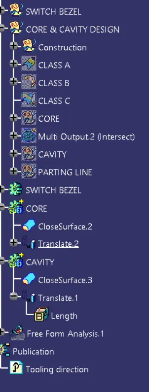
METHOD:
Step 1: Importing the Switch Bezel
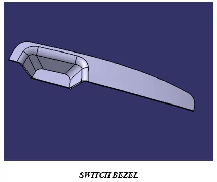
After importing the component, we need to analysis the drafts of that component for that need to determine tooling surface.
Step 2: Determine Tooling Axis:
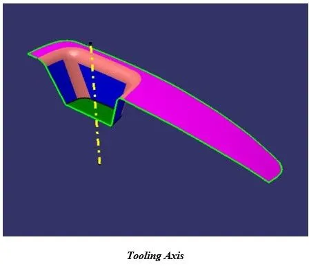
Create a Dummy Tooling Axis along the best possible direction as per the Class A as shown below. In this case, we have chosen Z-axis as a dummy as it doesn't interfere with any slots or holes or Create a new plane along XZ Plane and Intersect the plane and the Class A surface.
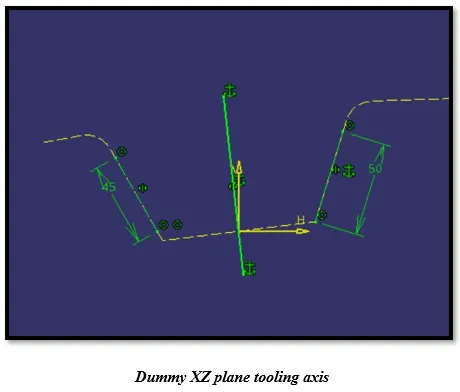
Create a new plane along YZ Plane and Intersect the plane and the Class A surface.
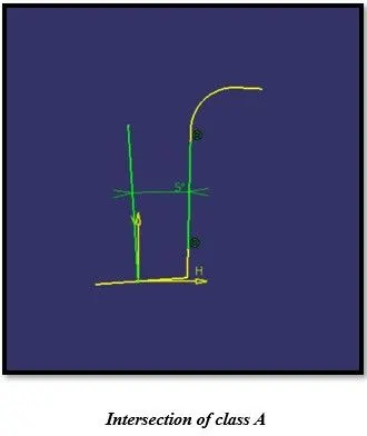
Create a Bisecting Line for the extended lines long the centre point and name it as Tooling Axis
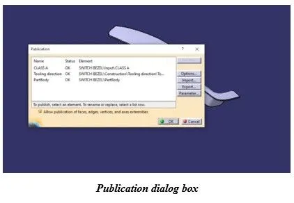
Now that the Tooling Axis is created let's Publish the Tooling Axis and the Class A Surface for quick access
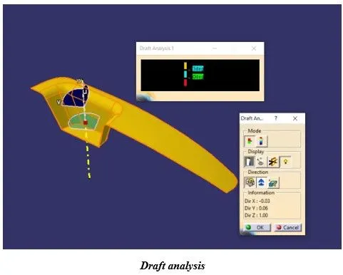
Step 3: Draft Analysis:
Change View Mode Customization to Material mode
Go to INSERT > ANALYSIS > FEATURE DRAFT ANALYSIS and move the compass to the Tooling Axis. Change the range to 3°. Apply the settings.
Uses the compass to define the new current draft direction.
Step4: Parting surface
First, we need to find the parting surface to spilt the component’s A, B & C surfaces.
Parting surface should not be in A surface of the component.
Parting surface is the spiting surface of core and cavity
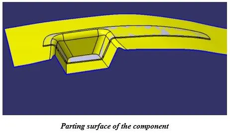
Step5: Core:
To create a Core, parting surface is to Trimmed with core surface
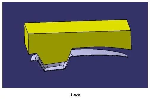
Core has a projection of the component and ejection pin helps to get the component out from the core.
Step 6: Cavity:
To create a Cavity, parting surface is to trimmed with cavity surface.
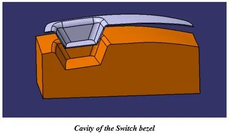
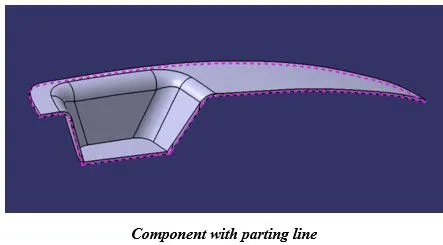
Parting line is junction between core, cavity and parting surface. On other word, parting line is where parting surface and component meets.
Parting line and surface are meeting the C & B surface, Hence the Class A surface will get the maximum surface quality.
RESULT:
The Switch Bezel has passed the Draft analysis test as the draft values of the Switch Bezel are higher than 3° and the Bracket is safe for production.
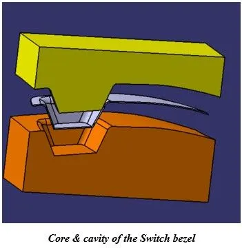
Hence, Created the cavity and core for switch bezel component through the given component. Created the tooling axis for the component which meets the requirements of the draft angle and the Draft analysis is analysed on the model.