Week 8 - Challenge 6 - Core & Cavity Design
SWITCH BEZEL CORE & CAVITY DESIGN
Objective:
- Creating the tooling axis for the given switch bezel model meeting the requirements of the draft angle and perform the Draft analysis on the model.
- Designing core & cavity of drafted switch bezel component.
Checking continuity of given class A surface:
First of all we have to check continuity of given class A surface to ensure class A surface is properly joined or no discontinuity present. This can be done using join or boundary command in CATIA . By looking visually in below image we see that surface has continuous connected boundry as highlighted by green line.
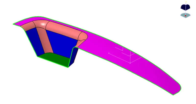
- Tooling axis direction:
Next step is to decide tooling axis direction. Tooling axis is a direction in which mould or core & cavity opens. Analyzing model visually to see which direction is most suitable for tooling axis. as shown in below image.
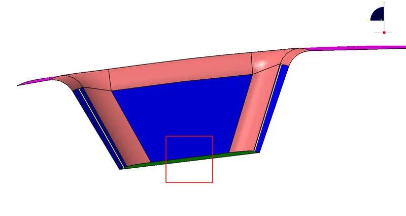
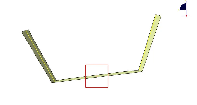
Now we have to see which surface will create problem or will be difficult for tooling. Because the surface which 90° to tolling axis will be cleared. So we have to check surface which lie parallel to tooling axis direction. Make line along parallel surface using point to point direction. Here we get two lines, now we will bisect the two lines & choose vertical direction.
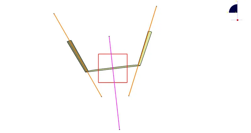
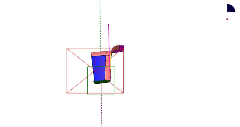
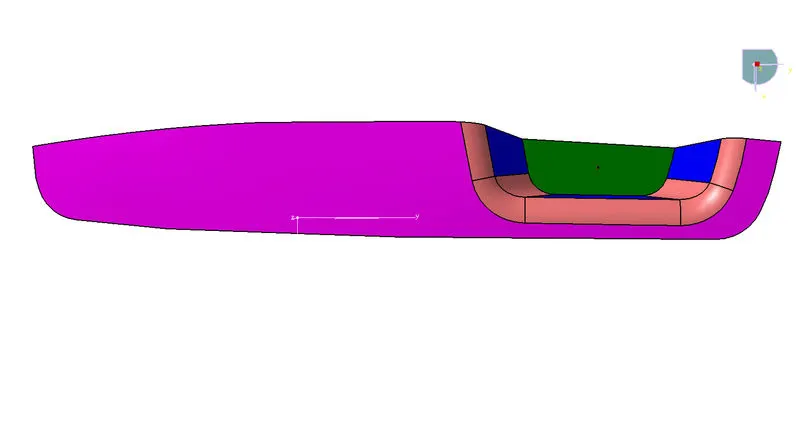
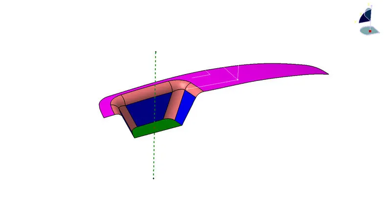
- DRAFT ANALYSIS OF COMPONENT ON DIFFERENT TOOLING AXIS
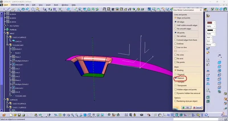
1.To perform draft analysis. Go to insert < Analysis< Feature draft analysis.
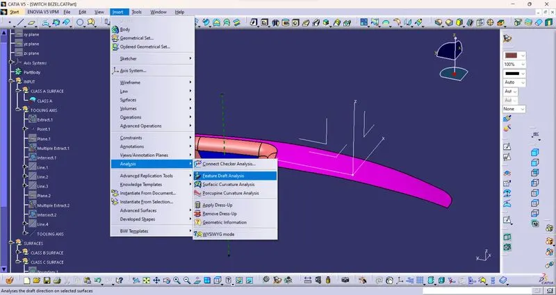
2. Switch customize view parameter mode to material.
- DRAFT ANALYSIS OF CLASS A SURFACE:
3D PART VIEWS
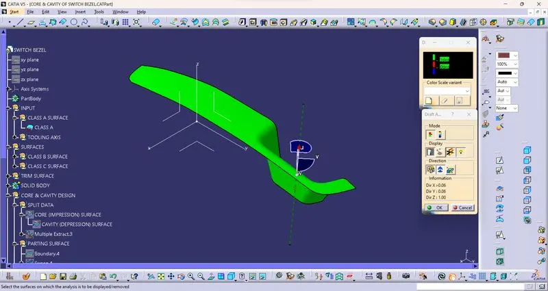
ISOMETRIC VIEW
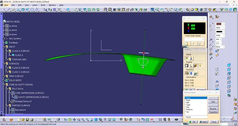
FRONT VIEW
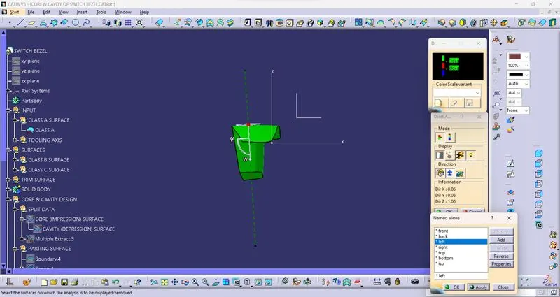
SIDE VIEW
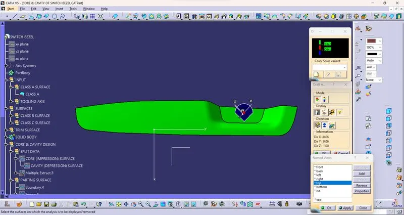
TOP VIEW
- DRAFT ANALYSIS ON SOLID BODY:
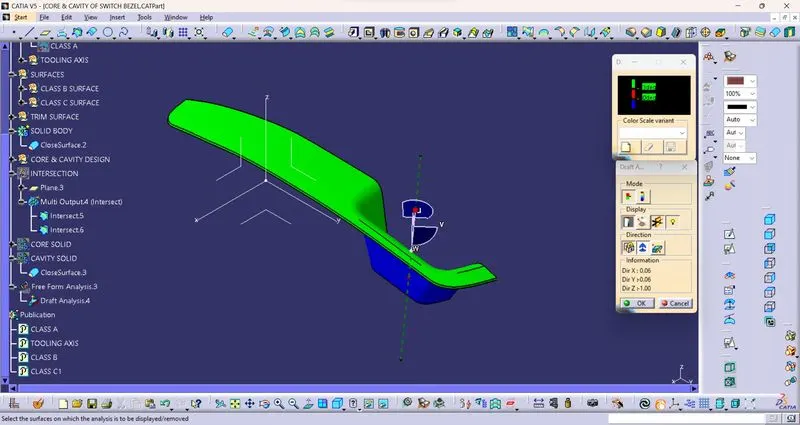
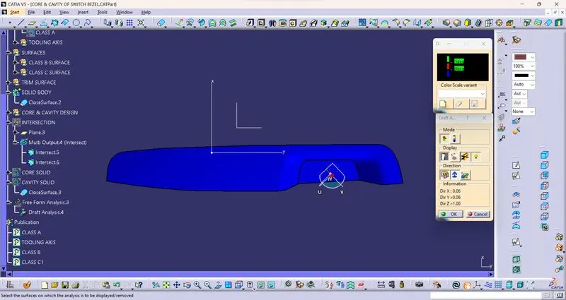
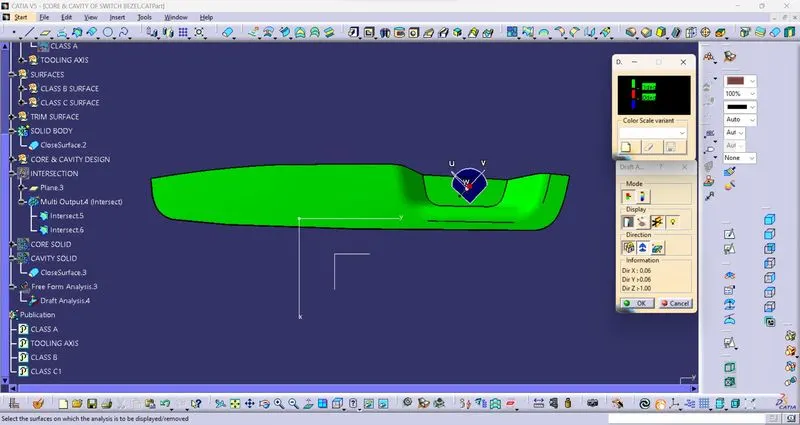
DIFFERENT VIEWS OF CORE & CAVITY DESIGN:
3D PART VIEWS
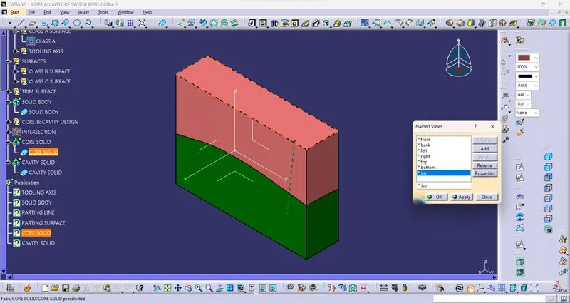
ISOMETRIC VIEW
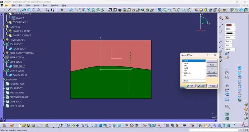
FRONT VIEW
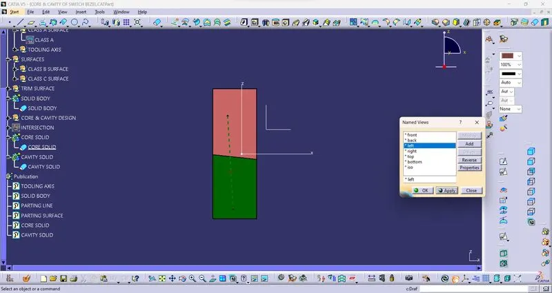
SIDE VIEW
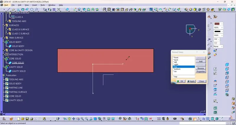
TOP VIEW