Designing Core & Cavity for an Interior Trim Arm Rest
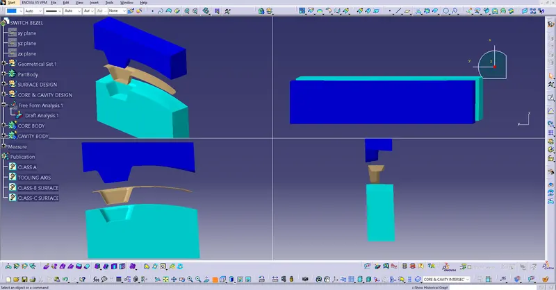
| CORE AND CAVITY. | The Dark Blue is the Core and the Light Blue part is the Cavity. The Core and the Cavity is Enclosed Together Under a certain Pressure and then the molten Plastic is Injected into the Cavity in between the Core and Cavity Part. |
|
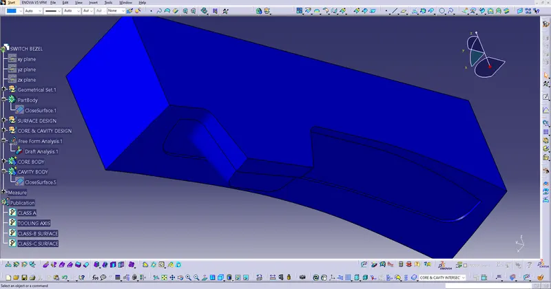
| CORE. |
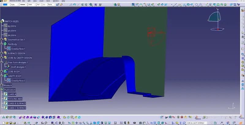
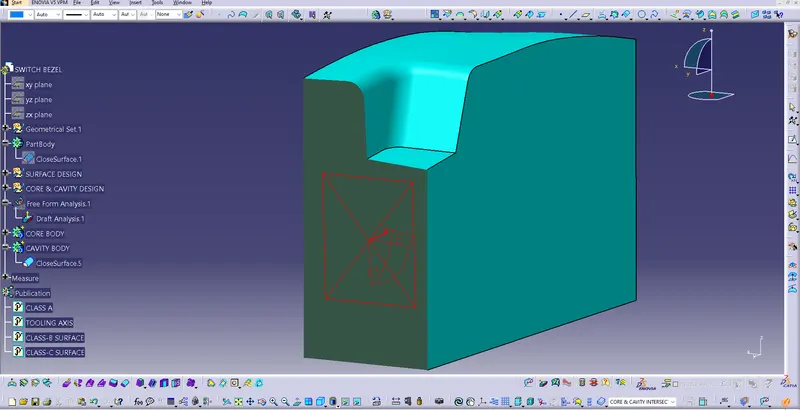
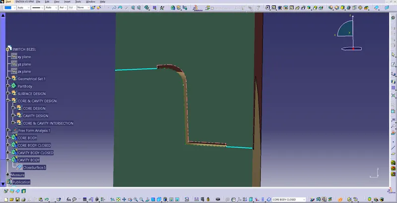
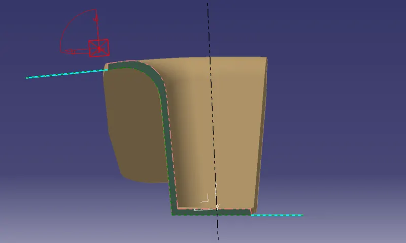
Core is the part that is on the Class-A side of the Design. The Images shows the Core Part and the section View of the Core of Switch Bezel. |
|
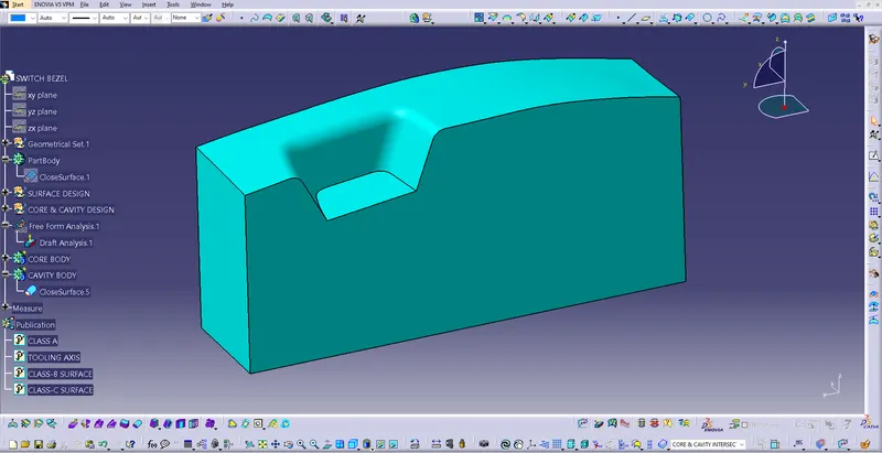
| CAVITY. |
Cavityis the part that is on the Class-B side of the Design. The Images shows the Cavity Part and the section View of the Cavity of Switch Bezel. |
|
| PARTING LINE |
Parting Line is the line that divides the core from cavity. It is Generally on the Cavity part as the Class-B Features are hidden fron the Consumers. |
|
TOOLING AXIS:
- Tooling Axis is very important part while designing the CLASS-B.
- The determination of the direction of Tooling Axis depends on the phases of the surface.
- The Bisecting Method of creating the tooling axis is first we create two lines to clear the draft analysis on both components X & Y.
- When we get both the lines we simply need to bisect it.
- The line formed by Bisecting those lines will be our Tooling Axis.
DRAFT ANALYSIS:
- Draft Analysis of a part is to check the phases of the Part are in given Draft angles.
- The tool Future Draft Analysis is used in CATIA V5 to anlyse the draft angles with respect to the created Tooling axis .
- If the colour code is OK as the given range then it is good to go.
- The green surface quote that the CLASS-A of the product is clered for further surface creation.