Week 8 - Challenge 6 - Core & Cavity Design
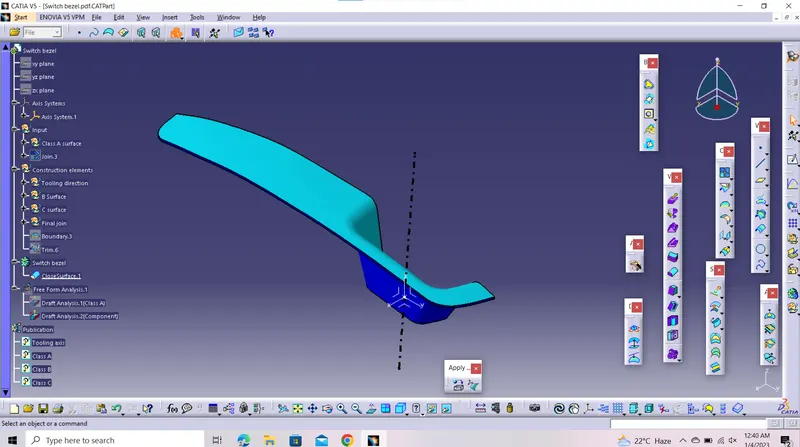
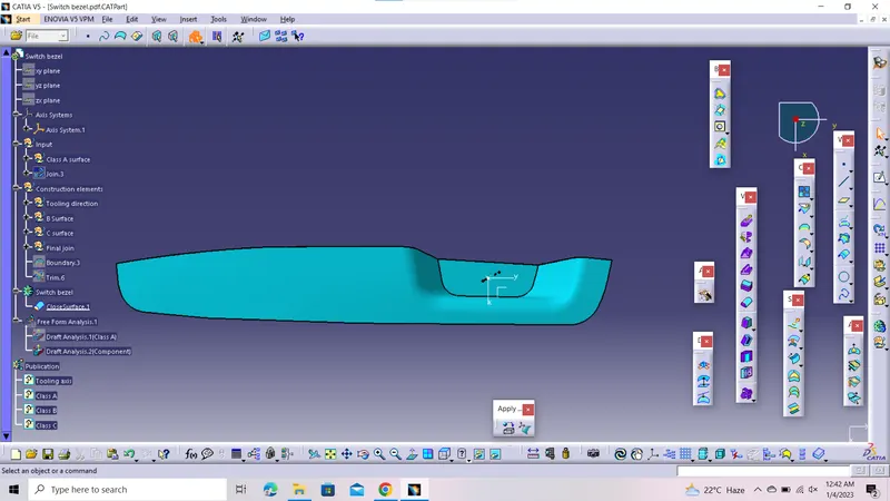
Creation of solid model of Switch bezel component using its Class A surface and to perform Draft analysis on Class A surface and also on Final output solid switch bezel and followed by designing of CORE BLOCK , CAVITY BLOCK and creation of parting surface and parting line for the created Switch bezel.
Major terminoligies :-
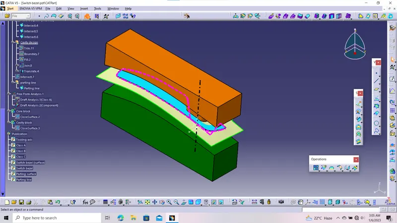
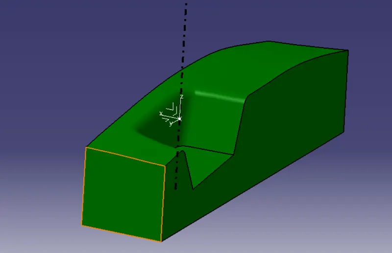
- Cavity block: Cavity is the upper half of the injection mold usually the show surface of the finished product but is mainly concave.In most of the cases, the cavity block has depression.
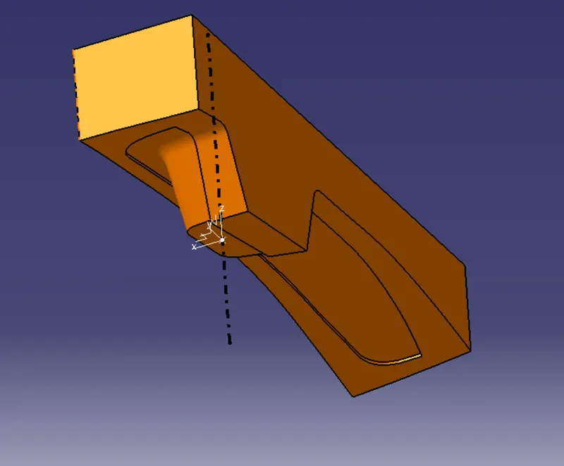
- Core block: Core is the lower half of the injection mold usually the show surface of the finished product and it is convex. Inn most of the cases, the core block has projection (ie., Die).(
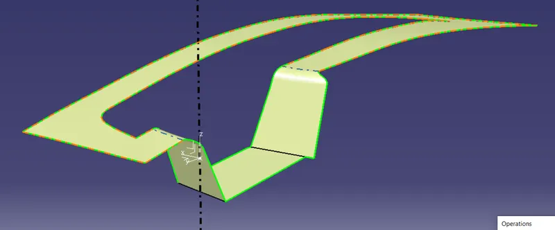
- Parting surface: The parting surface is the surface that lies between the core and cavity and THE PARTING SURFACE ALWAYS SHOULD BE DESIGNED ALONGSIDE OF CLASS B SURFACE ONLY.
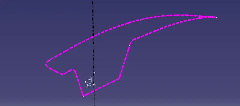
- Parting line: The parting line is the line that lies between the CLASS C and CLASS B along the parting surface.
Importance of Parting surface in designing of core and cavity:
This parting surface cannot be neglected while desining the core and cavity design. This parting surface is formed while moulding process, because of oozing out of injected melt plastic out of mold. we will pump the plastic granules, bit more than volume of mold because the melt plastic need to fill the complete mold and the oozing of plastic means that the mold is completly filled and there is no gap inside the mold.So, therefore we can conclude that, parting surface is the major criteria during desing of product, core block and cavity block.
Why Parting surface should be always should be designed alongside of ClassB surface but not to Class A surface?
The parting surface is the surface formed by ooze out plastic material from the mold while during molding process, it is the extra projection of mold and this is extra projection is unwanted and to be removed by some tooling process like trimming etc. After trimming there will be some creation of unwanted dents or rough finishing and these defects while trimming are common and to be considered while designing of core and cavity designing. So, Class A surface is the surface that is visible to the customer or user and there should be no surface defects and should lookk fine with surface finish but Class B is not visible and it lies inside the vehicle and covered by another part, so for that , we consider parting surface to be along side of Class B while designing.
Switch bezel:Switch Bezels in car are parts which contains switches and controls for different functions like Window control, Door lock/Unlock,Media and Temperature controls.
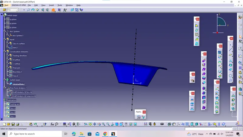
Steps followed to create Tooling axis:
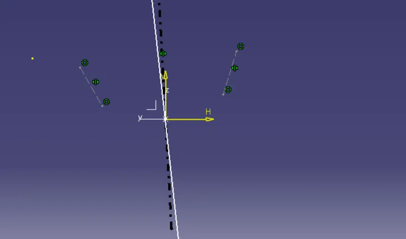
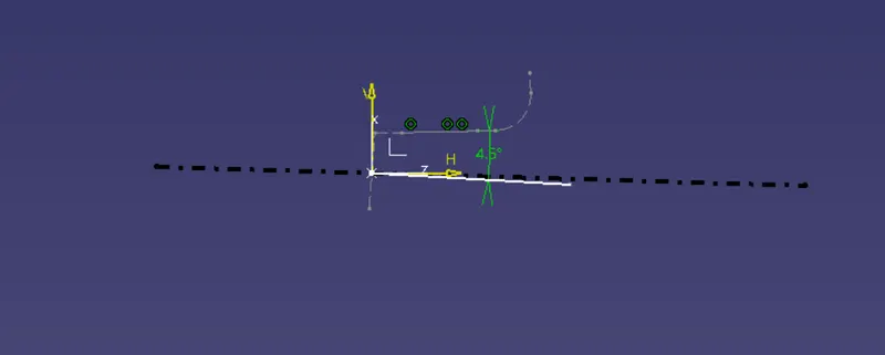
- Check the best possible side to create the tooling axis.In maximum case, we consider the bin type area to be were the tooling axis is to be passed through.
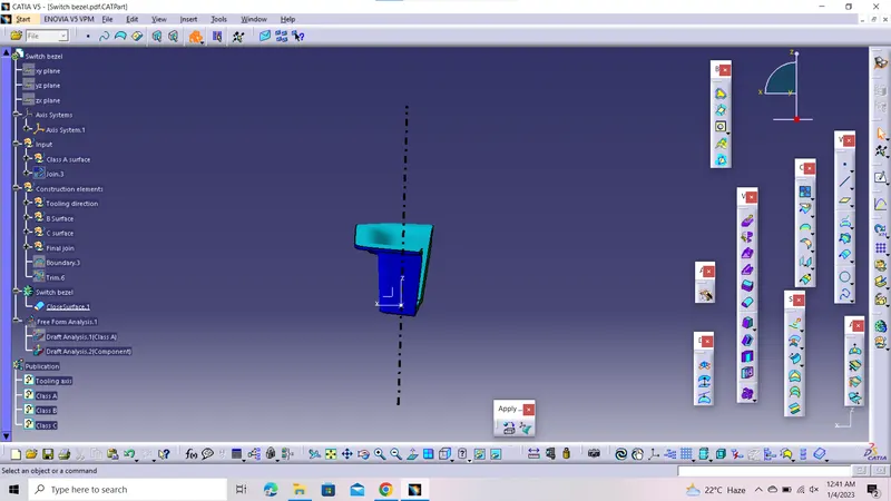
- So, here we can say that the Tooling axis is passing through the bin type projection , through the base .
- initialy, we extract the base surface and place a point on the centre of the extracted surface.
- make a intersection curve with reference to the point on the surface.
- Draw 2 line aling 2 side walls facing opposite to each other.
- Make a bisector with 2 lines and draw a line passing through the reference point with aligning at an angle of 4 degrees with the wall adjacent to the opposite one.
- Make another bisector with this line with the 1st bisector.
- 2nd bisector itself is the tooling axis of the model.
1)Steps followed in this project to create Class B surface:
- Here, the class B surface, is created by extracted induvidual patches from the class A surfaces and untrim it , followed by extrapolet and ofseting it to a value of thickness of 2.5mm
- Trim according to the Class A surface.
- Make sure , there is no gaps between the surfaces within B surfaces
2)Steps followed in this project to create Class C surface:
- Class C , in this project is created by extracting boundary edges of class A surface , make boundary with curvature continuity.
- Using sweep command , taking boundary curve as reference in along to draft direction at an angle of 3 degree create a surface along the edges of Class A surface.
3)Make sure, that the meeting edges osweep surface is not overlapping.If it occurs, then extrapolet the edges , that is overlapping .
4)Join the Class C and Class A surfaces
5)Trim the Class C and Class B surfaces.
6)Ensure that there is no gap between the surfaces.
7)Create a part body, With the command THICKNESS , make the surface model to solid model.
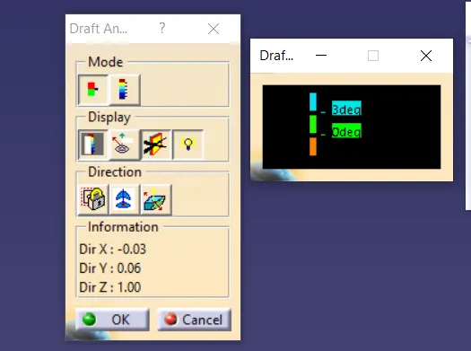
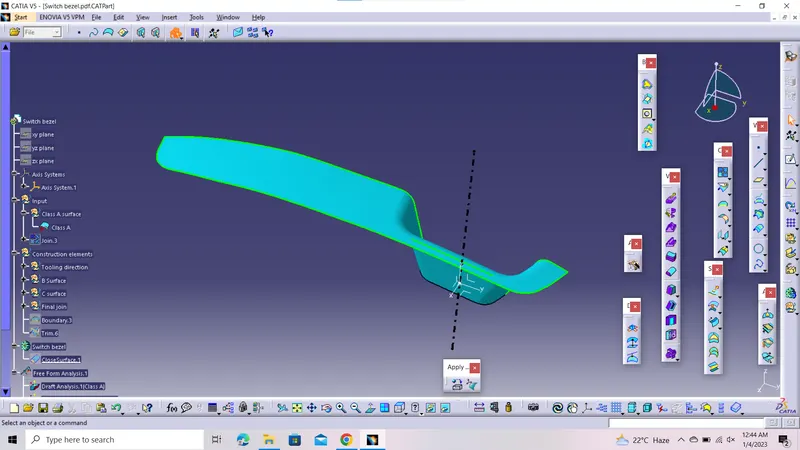
8)Steps to do Draft analysis on Switch bezel and its Class A surface:
- Select the angle range 0 to 3 degree with proper color code.
- Place the coordinate system on to the Tooling axis, which means we are arranging a coordinate system for drafting anlaysis.
- After proper arranging of coordinate system , lock out the view.
- Select draft option , and select the Solid switch bezel
- Same, above mentioned steps, are used to perform the draft anaylsis for Class A surface.
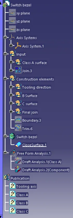
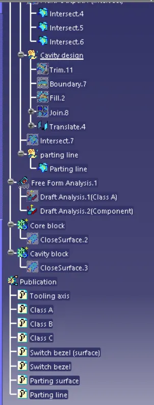
9)Publishing of Tooling axis, Class A suface, Class B surface and Class C surface is also done for easy accessible.
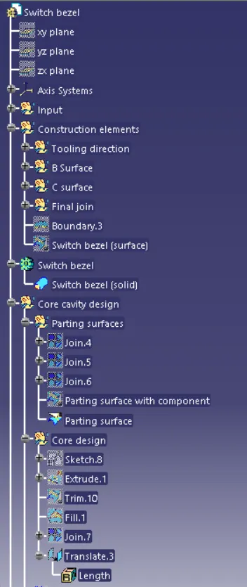
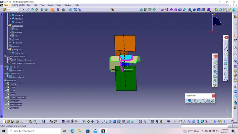
10)Steps followed to design Cavity block in this project:
- Cavity have depression, so Unhide the join of Class A& C and B , thenafter trim the both the surfaces.
- Make a sketch on zx plane, of rectangle , and ensure that the rectangle should cover the mould and does not exceed the parting surface.
- Extrude the rectangle and trim with the parting surface.
- Create the boundary on the bottom of the rectangle and fill it.
- Change the work bench and create the solid.
11)Steps followed to design Core block in this project:
- Core , so Unhide the join of Class A& C and B , thenafter trim the both the surfaces.
- Make a sketch on zx plane, of rectangle , and ensure that the rectangle should cover the mould and does not exceed the parting surface.
- Extrude the rectangle and trim with the parting surface.
- Create the boundary on the top of the rectangle and fill it.
- Change the work bench and create the solid.
12)Steps followed to design Parting surface in this project:
- Unhide Class B surface and Class C surface , theneafter trim the Class B using Class C inside.
- Resultant is Parting surface.
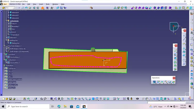
13)Steps followed to design parting line in this project:
- Make an intersection between the Class B and Class C surface.
- The resultant line itself is the parting line.