Week 8 - Challenge 6 - Core & Cavity Design
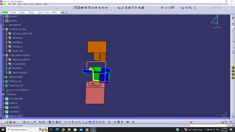
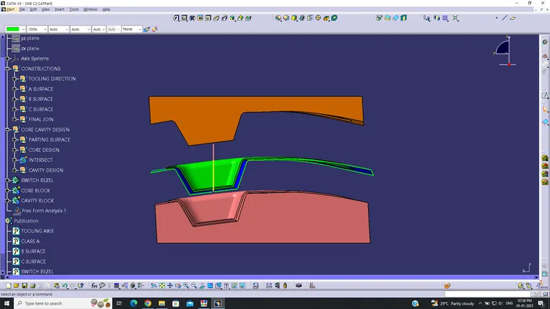
REPORT:
The tooling axis is created by creating a point on the center of the base of the switch bezel and then a dummy tooling axis is made by creating a line perpendicular towards the Z direction. Then an intersecting line is created at 6deg from the side walls of the switch bezel. Then using the Bisecting line tool the Main tooling axis is created by bisecting the intersect line from the side wall and the dummy tooling axis.
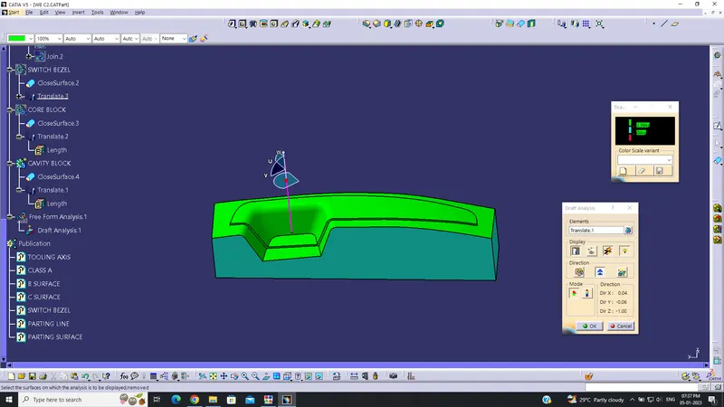
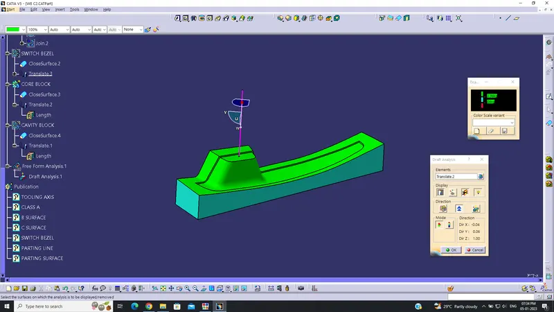
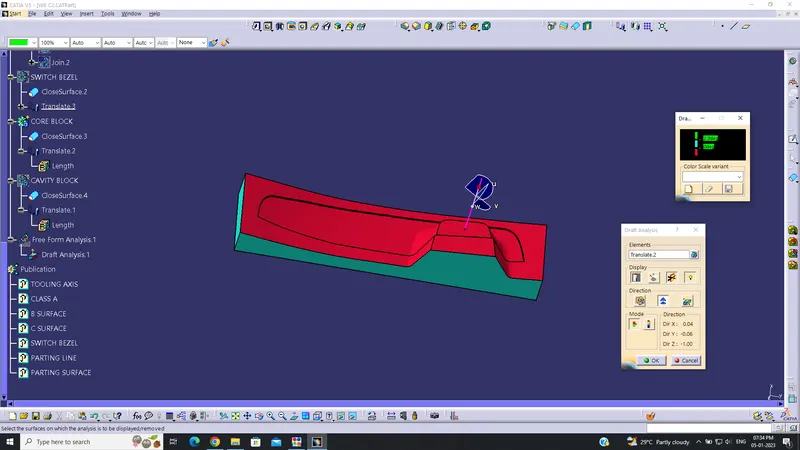
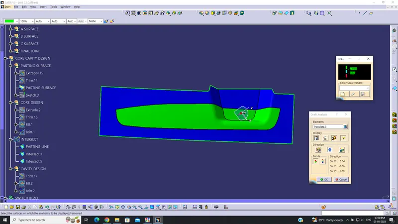
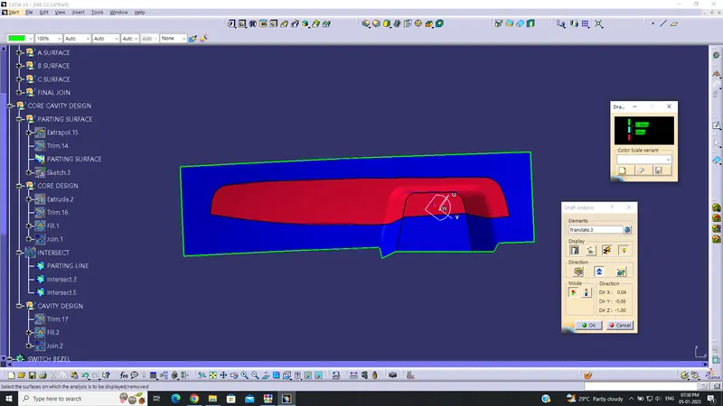
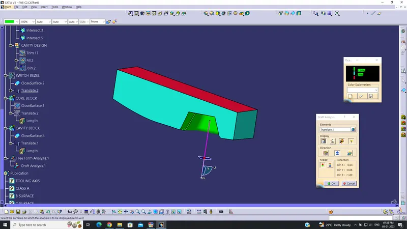
The drafting analysis is done on the tooling and a minimal draft angle of 3deg is provided as shown above. The drafting angle is provided at both sides on the class c surface. The draft is created along the Main tooling axis direction.