Week 8 - Challenge 6 - Core & Cavity Design
CORE AND CAVITY DESIGN
AIM
- To create th tooling axis .
- To create the solid body.
- To create the parting line and parting surface.
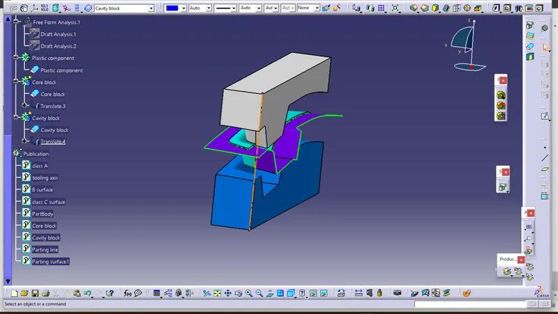
- To create the core and cavity for the component.
Creation of tooling axis
Initially the propable tooling direction is taken from the class A surface . In this model Z axis is the suitable direction for drafting.
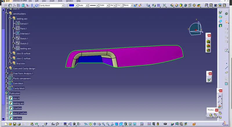
The flat surface is extracted from the class A.
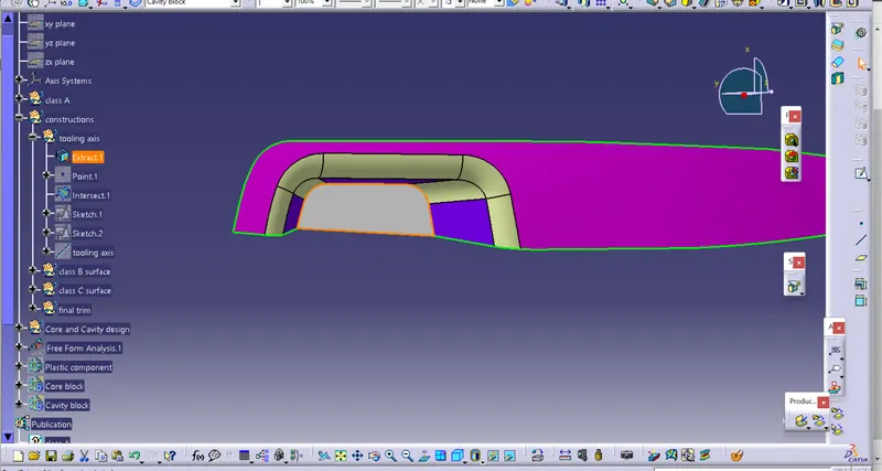
One center point is created on the extracted face .
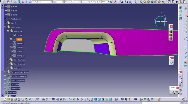
Then one axis system is inserted on that point
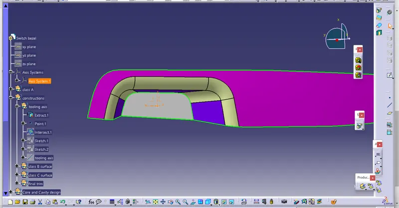
Intersection between the class A abd YZ plane of the axis system is takened.
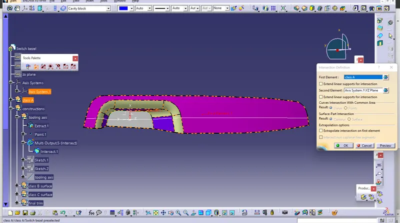
In YZ plane by using the positioned sketch the bisecting line is created inbetween the side walls of the pocket area.
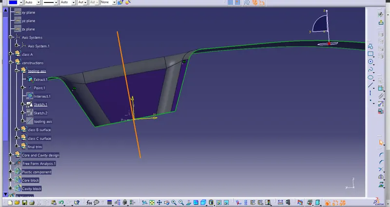
The another bisectiong line is created in between the ZX plane.
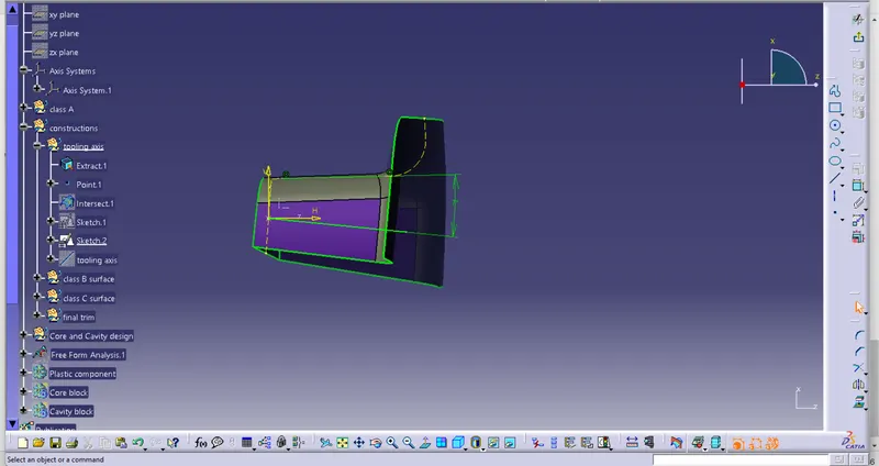
Finally the tooling axis is created by taking the bisecting of those bisected lines.
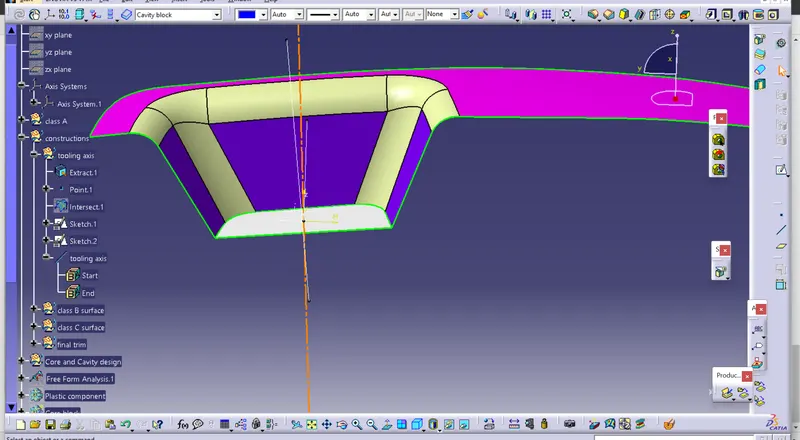
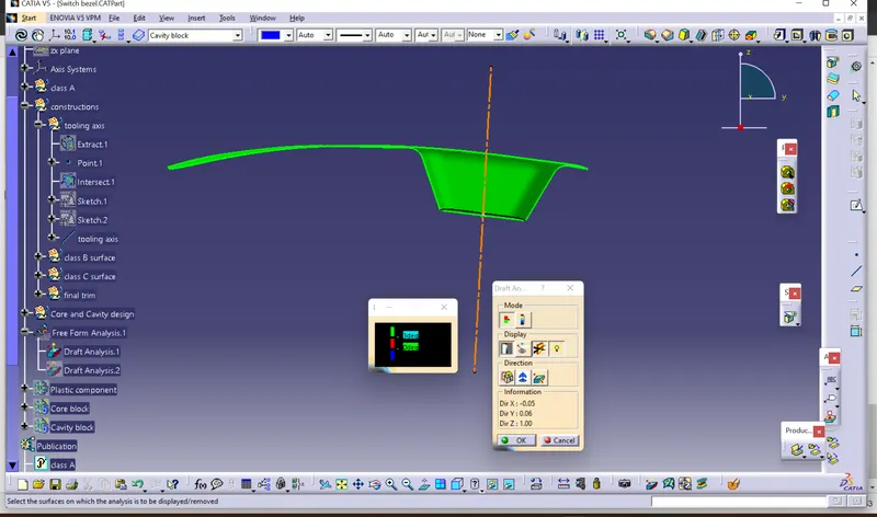
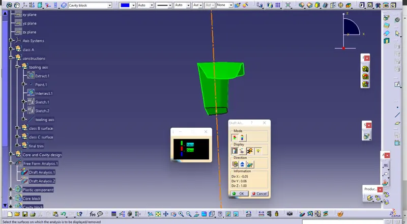
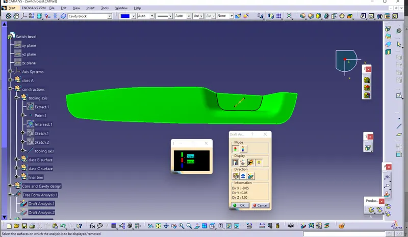
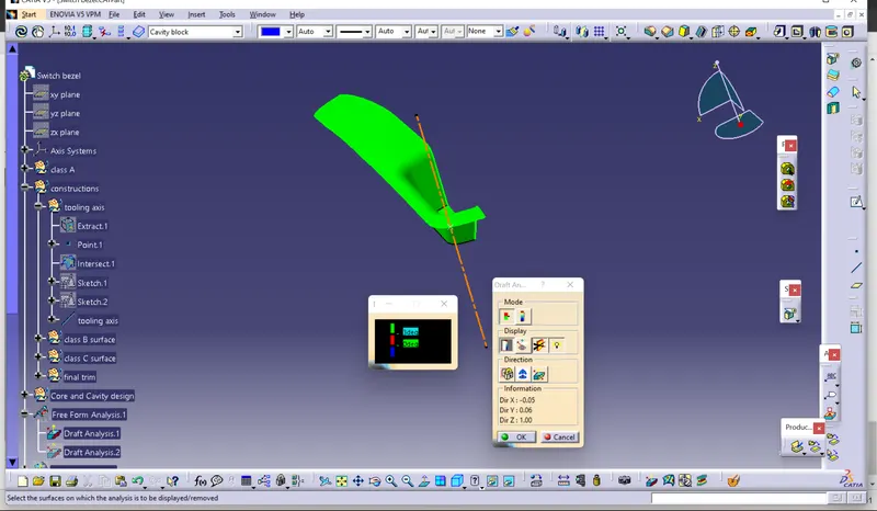
Draft analysis on the Class A surface
Front view
Side view
Top view
Isometric view
Draft analysis on Plastic component
Front view
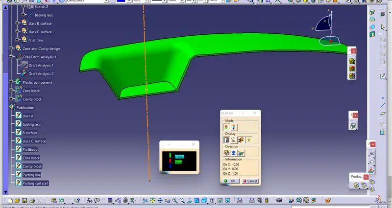
Side view
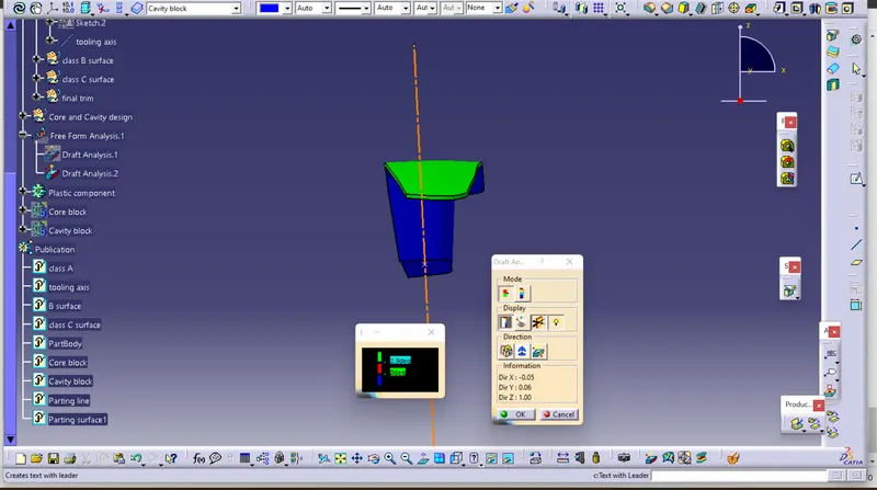
Top view
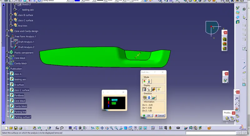
Isometric view
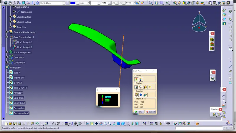
Parting surface
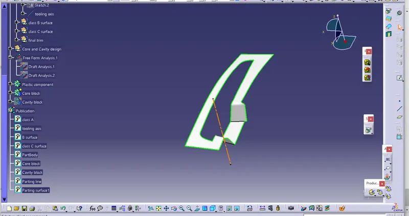
Core and Cavity block
Front view
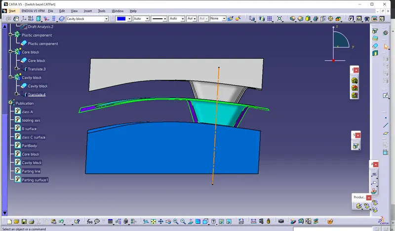
Side view
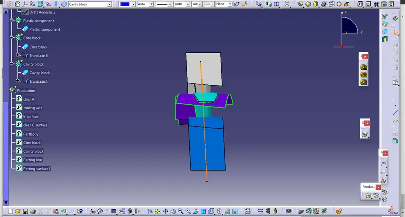
Top view
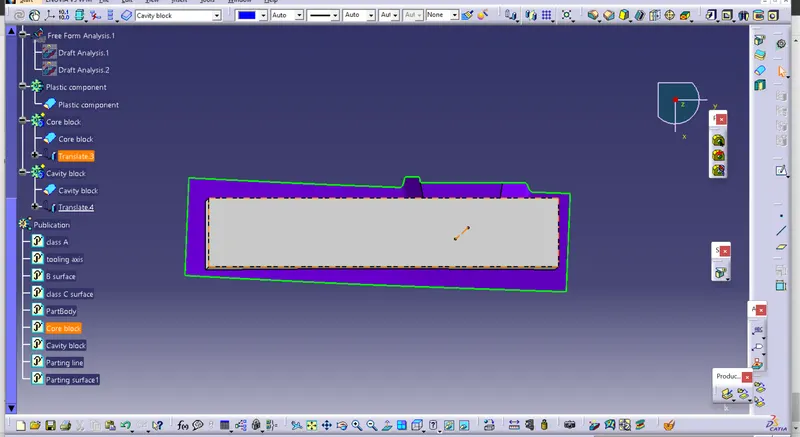
Isometric view
Conclusion
The switch bezel plastic component, tooling axis , parting line , parting surface and the core and cavity all are craeted . The draft analysis os performed.