Week 8 - Challenge 6 - Core & Cavity Design
Aim: Week 8 - Challenge 6 - Core & Cavity Design
Objective: Create the Core and cavity blocks for the switch bezel designed in the earlier challenge
- Tree Structure
- Tooling Axis
- Switch Bezel Solid / Surface body
- Parting Line and Parting Surface
- Ensure Proper Tree Structure
- Geometrical sets should have a proper name based on the sketches present inside of it
- All the sketches should be created under the Geometrical set
- Use the Close Surface feature to make a solid body from the surface.
- Publications: Use the publication option and publish the below
- Report
- A detailed report should be done explaining the draft analysis and the tooling axis creation.
- An explanation should be given on the way of creating the tooling axis, particularly the Bisecting method.
Submission Requirements:
- Submission in challenge box
- Screenshots of the Draft analysis report for both the switch bezel plastic component
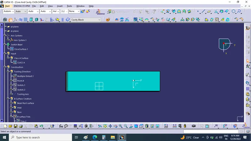
- Screenshots of the core and cavity blocks in various orientations (Isometric, Front, Side, and Top View)
- Below images/screenshots should be inserted into the challenge box
Description:
The main objective of this challenge is to design a Core and Cavity for a Switch Bezel' in CATIA V5 with the help of a surface workbench.
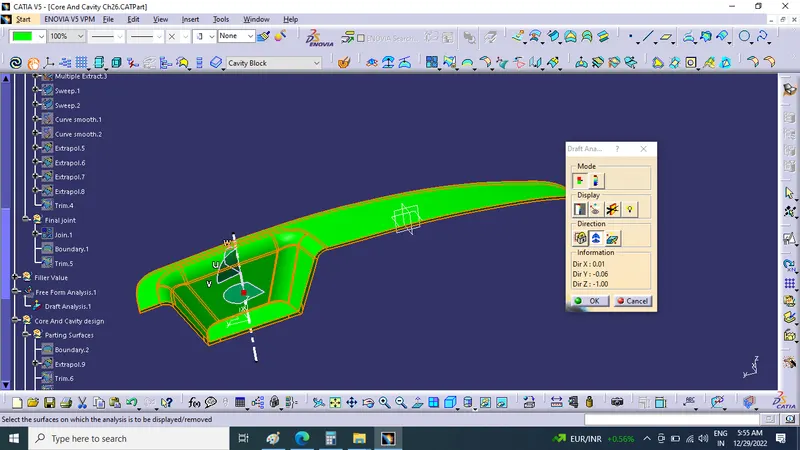
Tooling axis: The axis is the direction in which the mold opens or else the core and cavity open. The tooling axis should help to clear components from the core and cavity, so it plays a very crucial role in plastic designing and manufacturing also.Before we design the core and cavity, we should perform a draft analysis on the solid part body of the switch bezel.
Core Design:
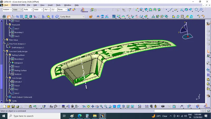
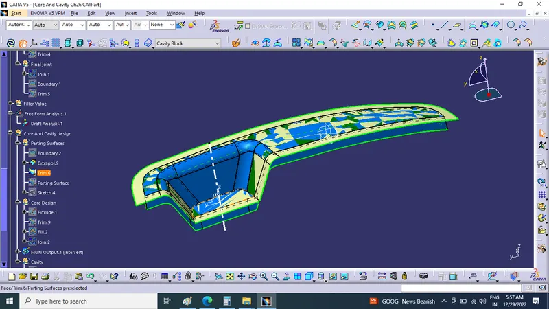
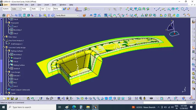
Initially, I have taken the boundary of the class A surface to extrapolate it. After extrapolating the class A surface I trimmed extrapolated class A surface and class C surface (join of class A and sweeped surface), after I trimmed the class B surface with Trim.5 to create the 'Parting surface'. Now I draw a rectangle, which does not exceed the boundary of the parting surface.
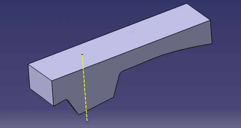
Now I extruded the sketch along the tooling axis, after extruding the rectangular sketch I trimmed both the parting surface and rectangular extrude to remove the lower side of the parting surface. I filled the upper surface to make a closed surface by joining the filled and trimmed surface. Now I make the closed surface into a solid body, the obtained solid part body is our CORE bock.
Extrapolated class A surface:
Trimming the class C surface with extrapolated class A surface:
Parting surface trim:
Rectangular sketch to extrude:
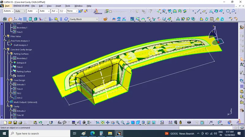
Rectangular extrude:
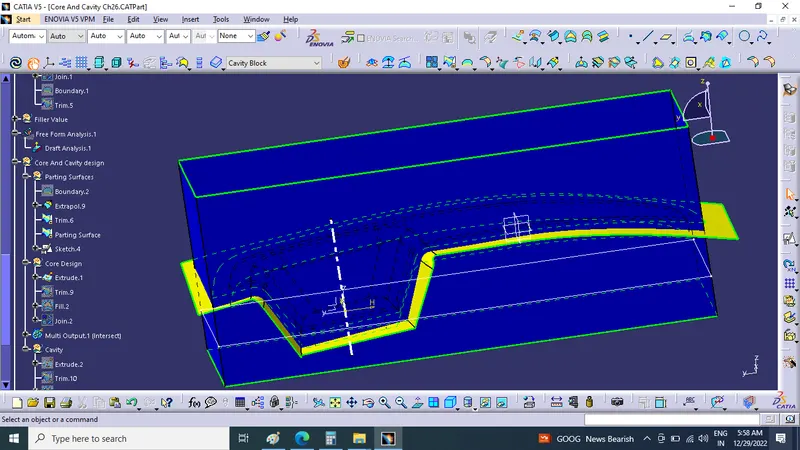 Core block:
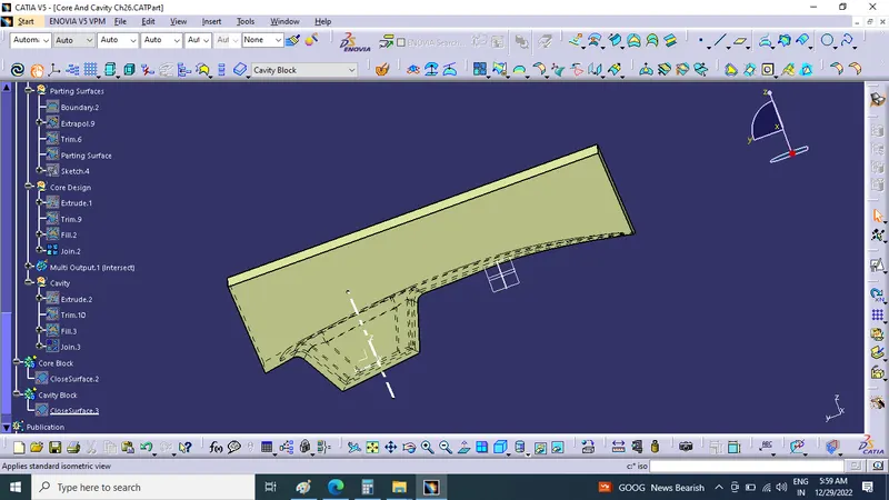
Core block:
Closed surface:
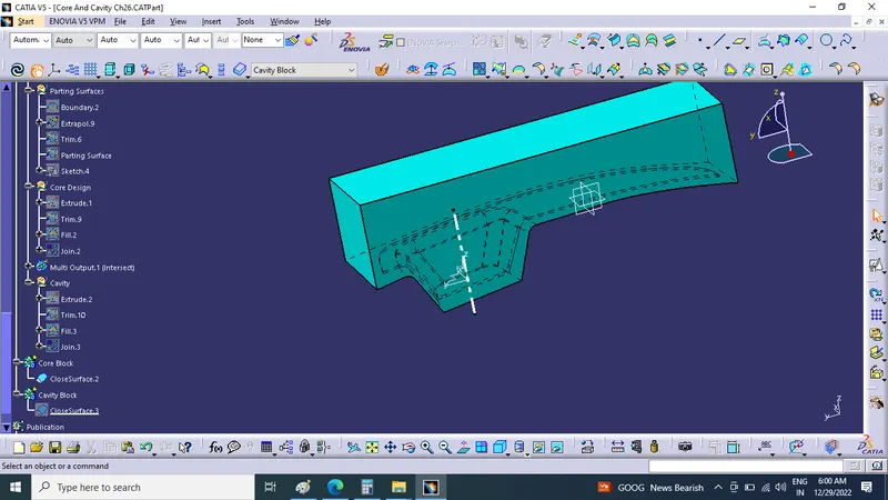
Core block solid:
Cavity Design:
To create the cavity block, I trimmed the rectangular extrude with a class B surface to remove the surface which is the upper side of it. After that, I filler the surface which is opened, to make a closed surface by joining both trim and filled surface. Now create a solid body from the closed surface by using the closed surface. The obtained part body from the closed surface is our CAVITY block.
Trin for Cavity block:
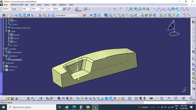
Cavity block:
Closed surface:
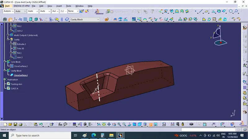
Cavity block solid:
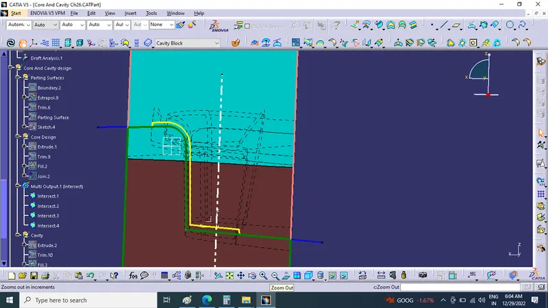
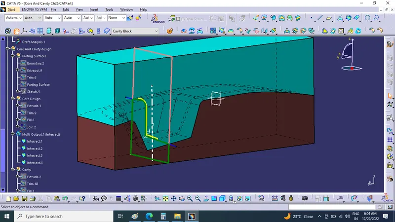
Parting line:
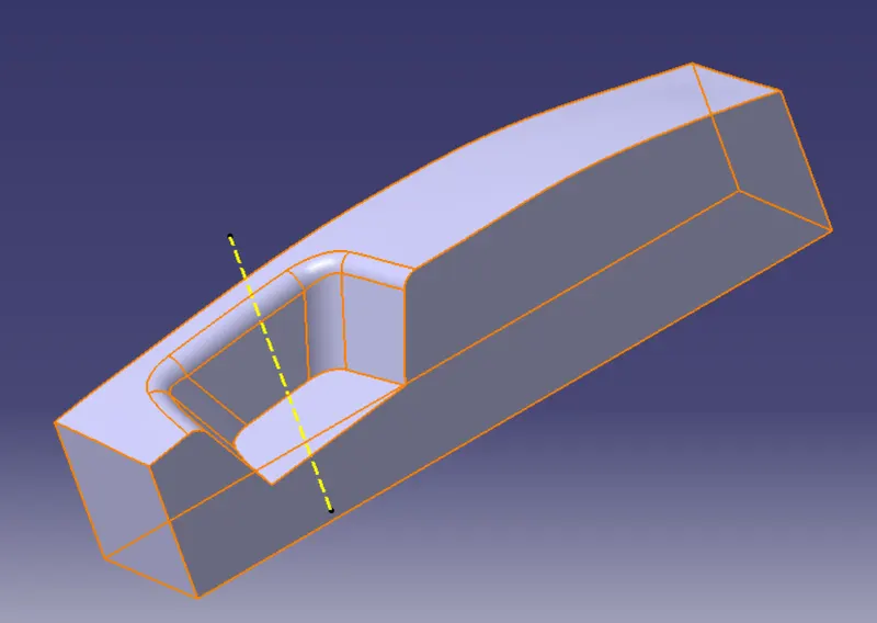
- It is the line where the core and cavity intersect each other.
- The parting line lies on the B surface of the Plastic component to protect the A surface from the splash.
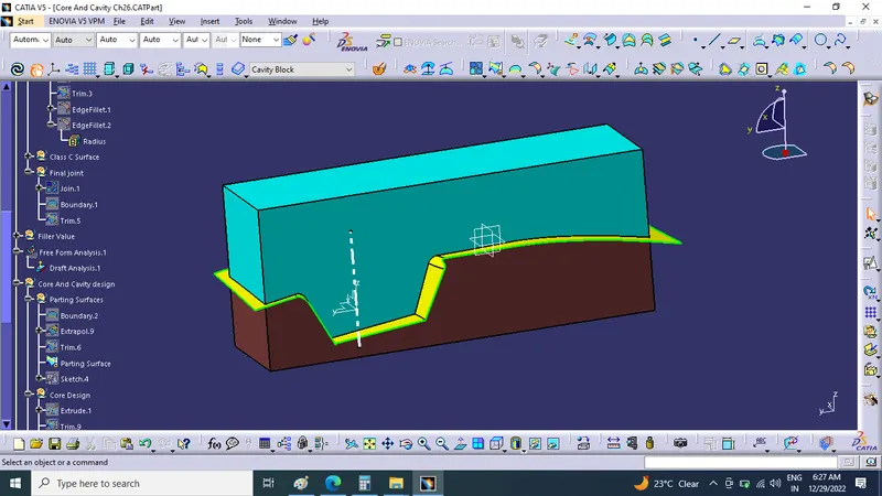
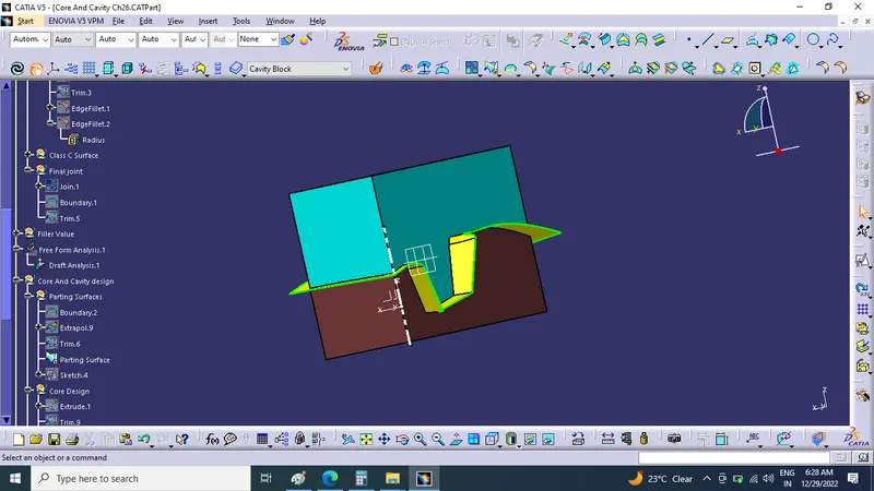
Parting Surface:
- The surface where the core and cavity meet each other is called the Parting surface.
- The Parting surface also lies on the B surface side.
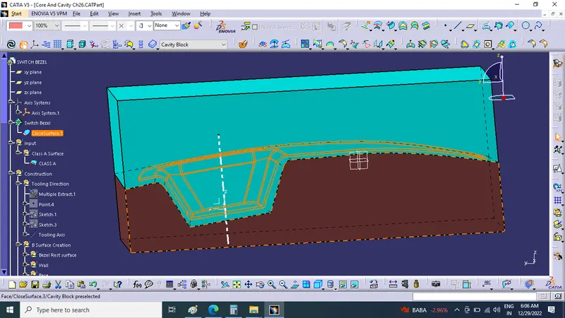
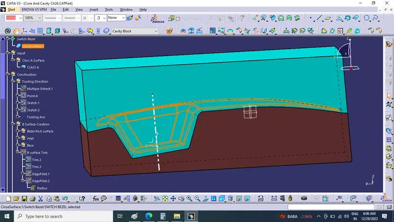
Tree Structure:
class A and Tooling axis:
Class B surface:
Switch bezel reset surface, walls and Base: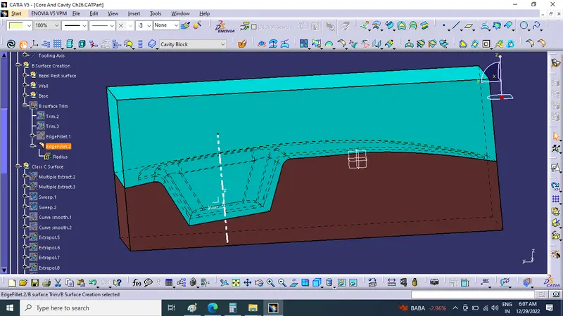
Class C surface:
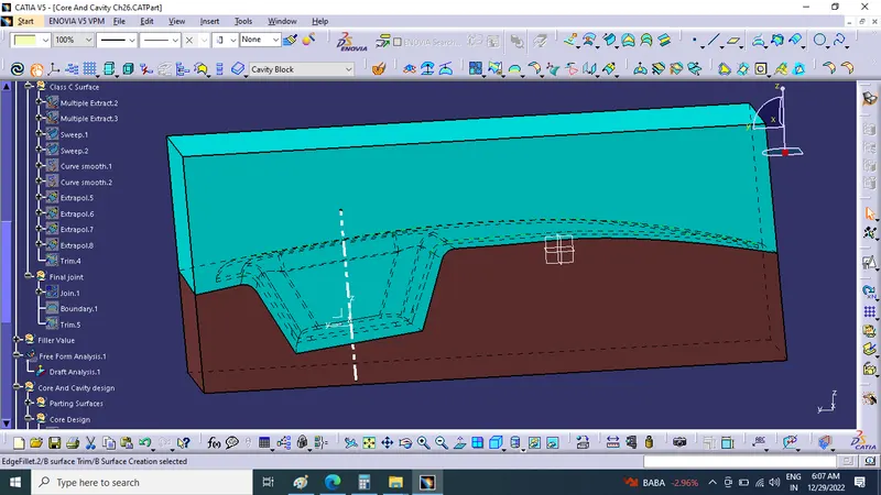
Part Area Between Core Block And Cavity Block By section View
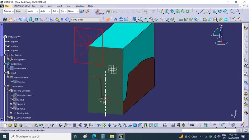
Parting surface and Core design:
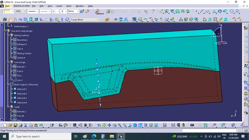
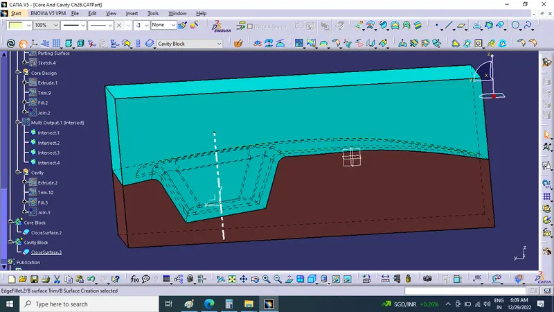
Cavity Design and Parting line:
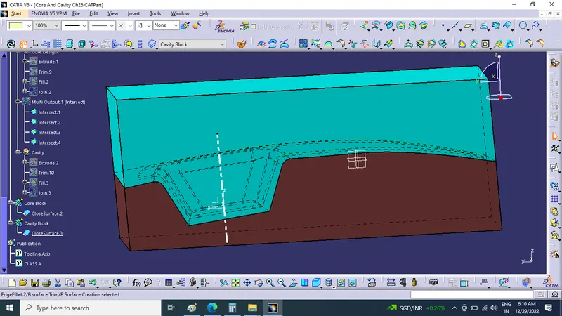
- Screenshots of the Draft analysis report for both the switch bezel plastic component
Part Bodies and Draft Analysis:
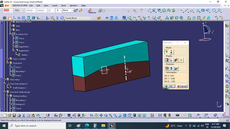
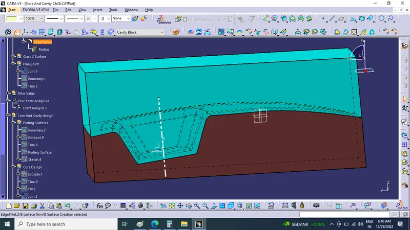
- Screenshots of the core and cavity blocks in various orientations (Isometric, Front, Side, and Top View)
Isometric view:
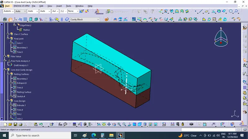
Front view:
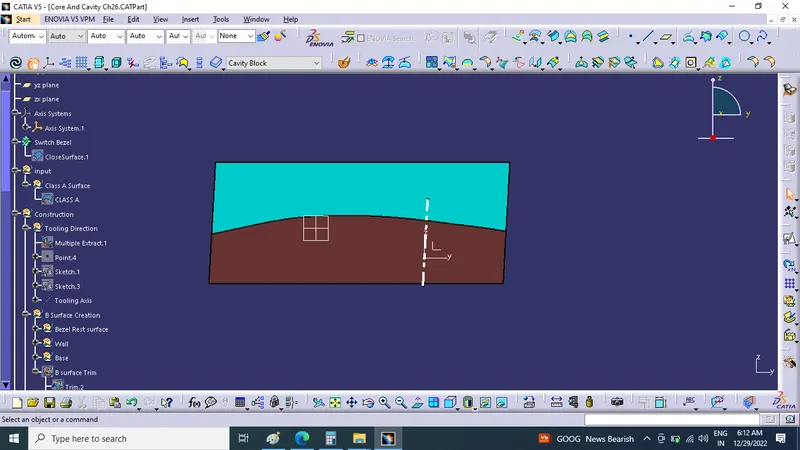
Right Side view:
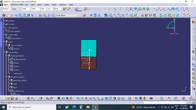
Top view:
- CATpart zip file is submitted as an attachment using the below Browse option.
Conclusion:
- Here successfully done challenge Create the Core and cavity blocks for the switch bezel designed in the earlier challenge. and the CATPart file is attached below using the Browse option.