Week 8 - Challenge 6 - Core & Cavity Design
AIM: Create the Core and cavity blocks for the switch bezel
OBJECTIVES:
- Creation of tooling axis for the given Class-A Surface
- Conduct draft analysis of the model.
- Create parting line and parting surface for the component.
- Create the Core and cavity blocks for the switch bezel solid.
INTRODUCTION:
In this project, we are designing core and cavity blocks from the switch bezel plastic component using Catia software.
Draft
In engineering, draft is the amount of taper for molded or cast parts perpendicular to the parting line. It can be measured in degrees or mm/mm (in/in)
- Drafts (or taper) in a mold, facilitate part removal from the mold. The amount of draft angle depends on the depth of the part in the mold, and its required end-use function.
- The draft is in the offset angle in a direction parallel to the mold opening and closing.
- It is best to allow for as much draft as possible for easy release from the mold. The minimum taper angle is 0.5 to 1 degree but 3 degrees is a widely accepted norm.
- The mold parting line can be relocated to split the draft in order to minimize it. If no draft is acceptable due to design considerations, then a side action may be required at a greater expense in tooling.
Draft Analysis
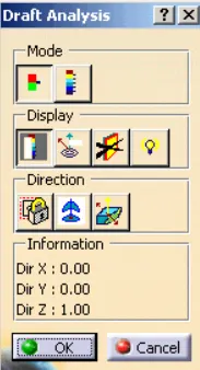
Displays a color gradient on the faces of selected bodies to help evaluate the manufacturability of your design. Select the bodies to evaluate and the axis to define the direction. Use the options to refine the gradient display. In Catia, we use the feature draft analysis tool for this.
Tooling Axis
It is the direction in which the mold or core and cavity open is the tooling axis.
Bisector Method: It is a common method used to create a tooling axis for Class-A surface, firstly select the direction in which tooling is difficult there may be one or two directions on a single surface. Then, create an intersecting curve with respect to the surface by taking a plane as a reference and draw lines that coincide with the intersection curve where the draft occurs, then bisect these lines to get the tooling axis. Use this method in another direction if needed. Finally, bisect those axes to get the tooling axis for the surface.
Class-A
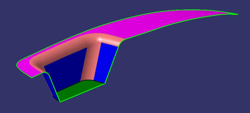
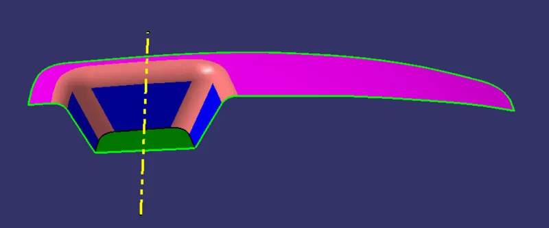
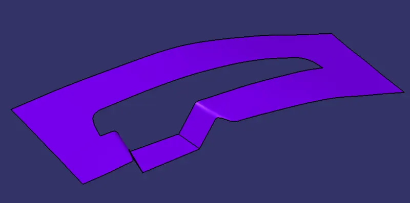
Class-A surface given to us
Creation of Tooling Axis for the Switch Bezel
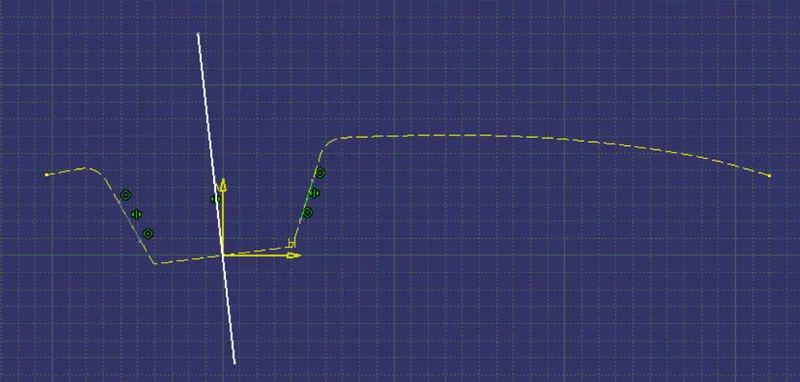
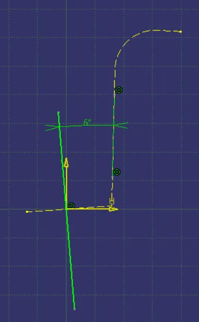
Tooling axis can be created using the bisector method. In this problem, we selected base plain surface as reference by creating a center point. Then, create an intersection curve with respect to a plane (reference as yz plane) then create lines corresponding to the draft then make a bisector with respect to the lines. But there is a draft in x direction also to be considered for creating the tooling axis. For that we created a intersection curve with reference as zx plane, but there is no symmetrical side for using the bisecting method so we give an angle of 6 degrees for tooling axis. After, we create a bisecting line for both this, ie our tooling axis
Draft analysis of Class-A Surface
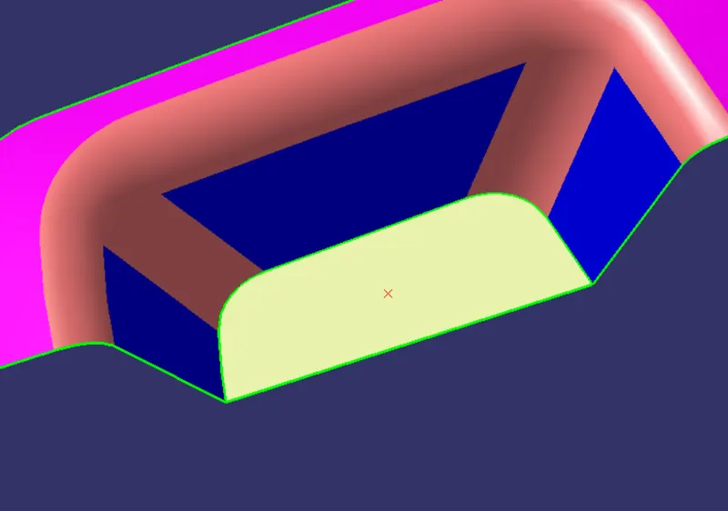
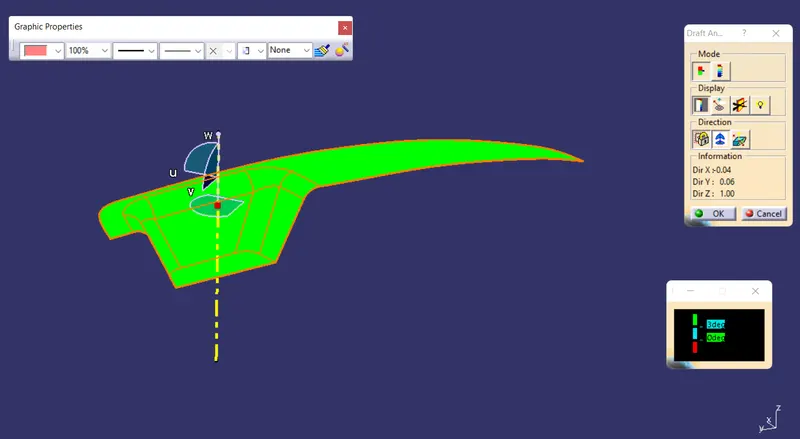
Draft analysis is conducted with a limiting value of 3 degrees.
Color scale used:
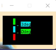
The green color indicates the draft angle is more than 3 degrees
Draft Analysis of Final Plastic Component
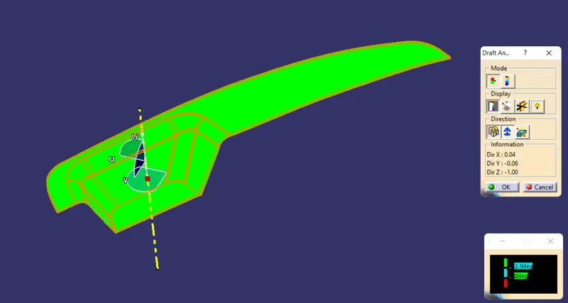
Color scale used:
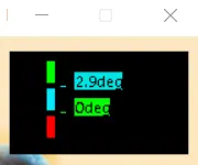
Draft above 2.9 degrees is shown as green. Below 0 degrees are shown as red. We give all drafts with a standard value of 3 degrees but it might vary in some portions that's why we give 2.9 degrees for draft analysis.
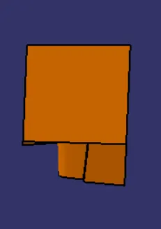
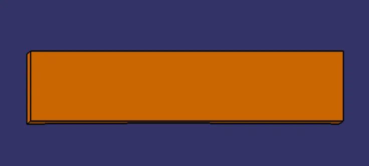
Core
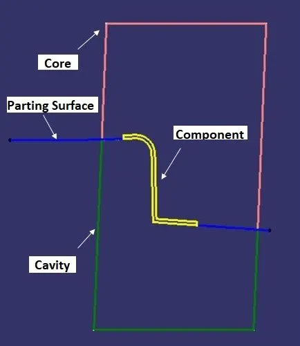
Core is a pre-prepared shape of the component. It is used to provide internal cavities, recesses, or projections in the molding.
1. Isometric View
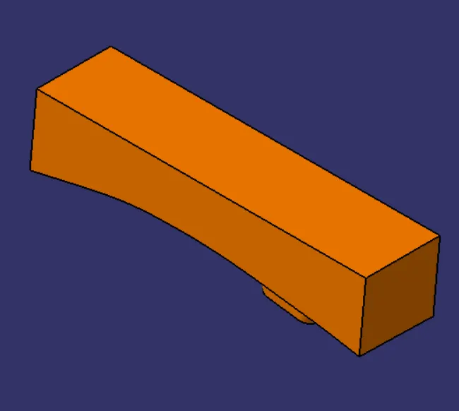
2. Front View
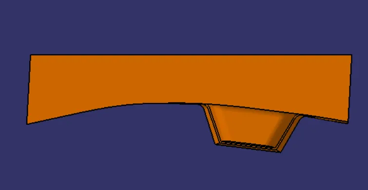
3. Side View
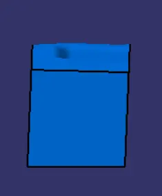
4. Top View
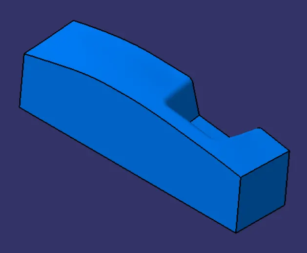
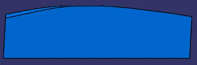
Cavity
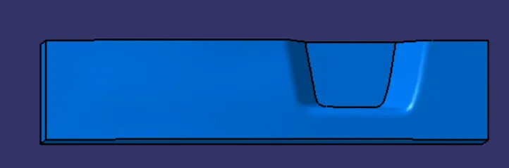
Cavity is the upper half of the injection mold usually the show surface of the finished product but is mainly concave.
1. Isometric View
2. Front View
3. Side View
4. Top View
Parting Line
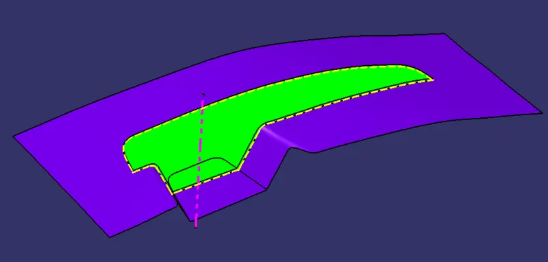
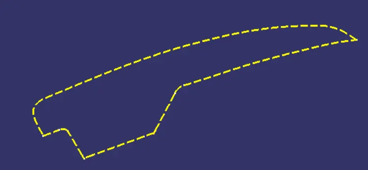
Parting Lines. A ‘parting line’ is the line of separation on the plastic part where the two halves of the plastic injection mold meet.
Parting Surface
Designed for the removal of the plastic product and the cold slug, the parting surface is where the core meets the cavity and is usually located at the largest section of a product.
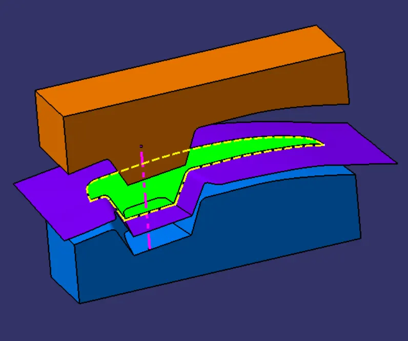
Intersection View
Combined View
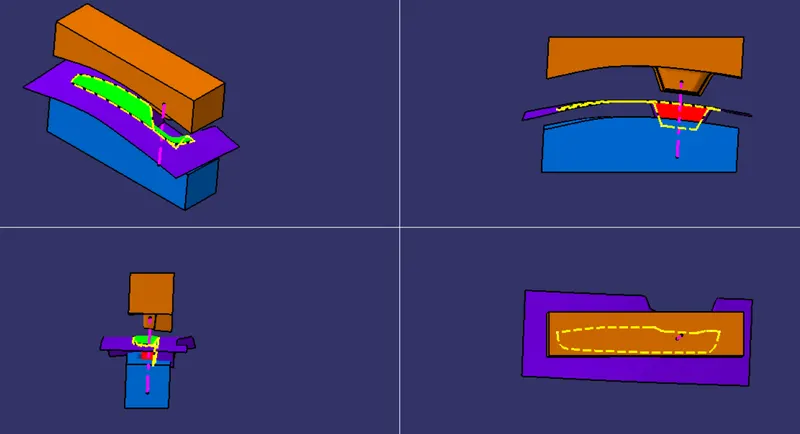
Different Orientional Views
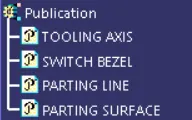
Publications
CONCLUSIONS:
- Tooling axis for the given Class-A Surface is created.
- Draft analysis of the model is conducted.
- Parting line and parting surface for the component is created.
- Core and cavity blocks for the switch bezel solid is created.