Week 8 - Challenge 6 - Core & Cavity Design
Aim
To create the CORE CAVITY with the given Class-A Surface using CATIA V5 tool.
Objectives:
- To create a Tooling Axis.
- To create parting line and parting surface
- To create Core and Cavity with the given Class A.
Design Constraints:
- ALL SURFACES SHOULD BE CLOSED BEFORE CONVERTING TO SOLID.
- ALL FACES SHOULD MEET THE ALLOWED DRAFT REQUIREMENTS.
Introduction:
Creating tooling axis.
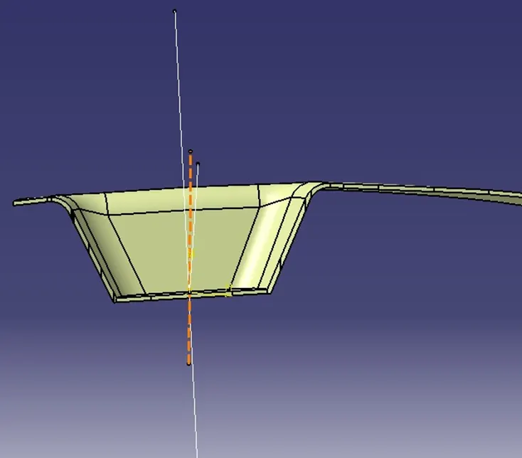
- A dummy Tooling axis is created using a reference point created on a hole of the given surface.
- Create an intersection of CLASS A surface with YZ plane.
- Tooling axis is created from these two lines as shown in above image using Bisecting option.
- The dashed line shown in figure is the tooling axis.
Creating a Parting surface from class A.
Parting Surface
The parting surface of a mould are those surface of both mould plates adjacent to the impressions to form a seal and prevent the loss of plastic material from the impression.
Creating a Parting line.
Parting Line
A parting line, in industrial casting of mould is the border line in which draft angles change direction. That is, it is the dividing line that splits the core and cavity halves of a moulded part. It is sometimes a starting point for the mould parting surface.
Creating a Core design & core block by close surface.
Core and Cavity
The core & cavity are the shaped sections in either half of the mould tool which give the plastic product its final shape. The hot molten material is injected into the core & cavity and then sets hard into shape. The design of the core & cavity is essential in the correct formation of the product.
Procedure
Creation of Parting Surface & Parting line
Parting Surface:
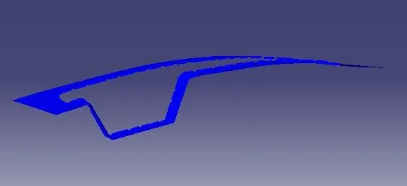
- Extract Class A surface boundary lines with boundary option.
- Extrapolate the Class A surface by 15mm.
- Trim the extrapolated surface with Class C & B surfaces respectively(In figure:Blue coloured surface is the parting surface)
Parting Line:
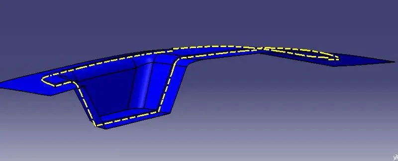
- Create Parting line with intersection with trim of A & C as well as Class-B surface.
- Apply line type, colour and thickness.(Yellow line as shown in the figure below)
- Create SPLIT with Parting line & Class-B surface
Design of Core & Cavity
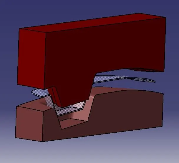
Design of Core:
- Open new sketch in XY plane.
- Create a rectangle and constraints it.
- Extrude the sketch on both sides with respect to tooling axis.
- Trim the parting surface with the above surface of the rectangle.
- Fill the open surface with the Fill / Extrude option.
- Join the filled surface with the trimmed surface.
Design of Cavity:
- Trim the extrude surface along the tooling axis with B surface.
- Fill the open surface with the Fill / Extrude option.
- Join the filled surface with the trimmed surface.
- Create closed surfaces.
Draft Analysis
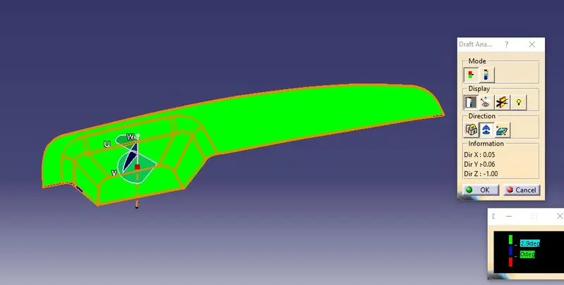
- From the Insert menu select Analysis option.
- Select Feature Draft Analysis.
- Select the Material option and drag the compass and place on tooling axis.
- Click on the surface.
- Make sure that the top surface is in green colour as draft angle should not exceed 3deg and click on OK option.
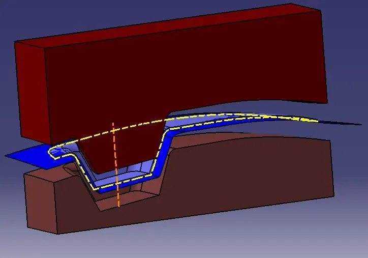
Isometric View
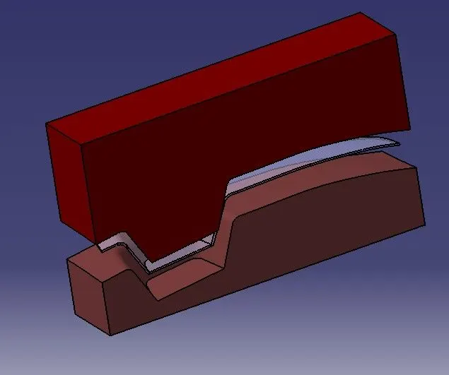
Front View
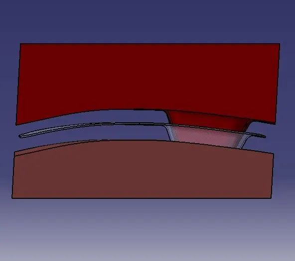
Side View
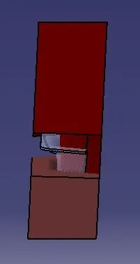
Top View
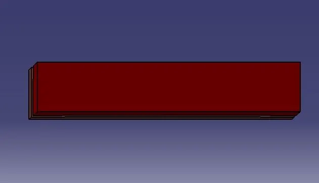
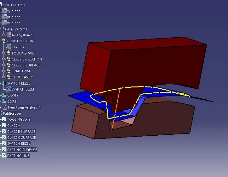
Tree Structure
Conclusion
Final output “CORE AND CAVITY” is successfully designed using CATIA VS tool.