Week 8 - Challenge 6 - Core & Cavity Design
Creation of Tooling Axis by Bisecting Method:
1. Extract the surface where the tooling axis is gonna come.
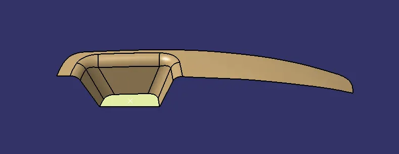
2. Create a point on the center of the extracted surface.
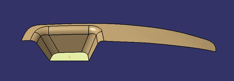
3. Then create the intersection of 3D component and draw the lines on the inclined intersection line and make them as construcion element. Draw the bisecting line with the drawn two lines and the middle point.
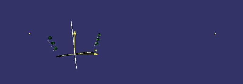
4. Create intersection of 3D element on other side and draw the line on the inclined intersection line and make them as construction element. Draw a line normal to the plane and constrain the created two lines with minimum degree.
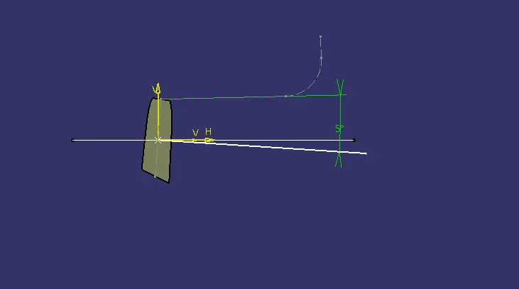
5. Then after creating the lines create a bisecting line with these two lines and a point.
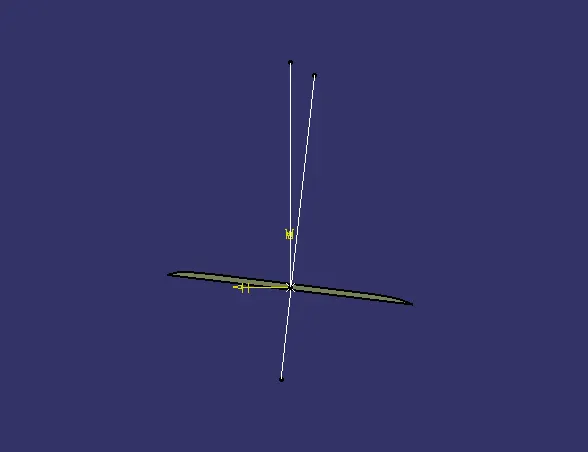
6. Middle line between those two lines is our tooling axis.
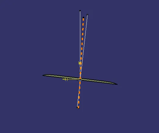
Draft Analysis on Class-A Surface:
1. Change the surface to material mode to start draft analysis.
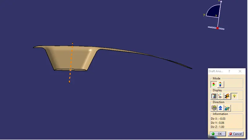
2. Zoom out and click & drag the compass to place it on the tooling axis.
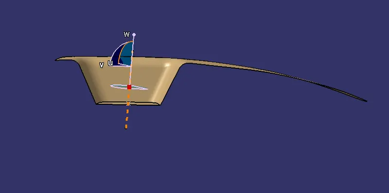
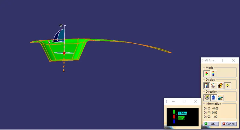
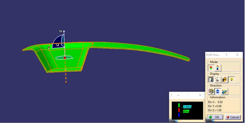
3. Click on the surface anywhere to start draft analysis. GREEN color shows the surface is more than 2.9 degree.
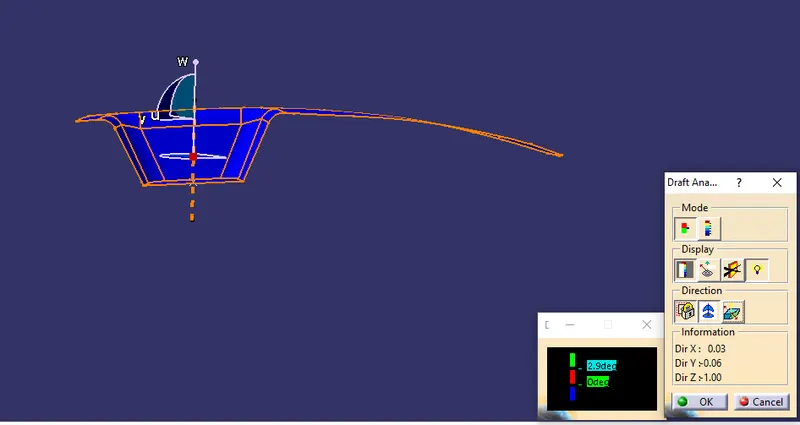
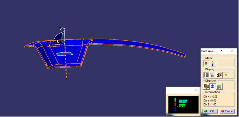
4.Then click on invert draft surface. BLUE color shows the surface is less than 0 degree.
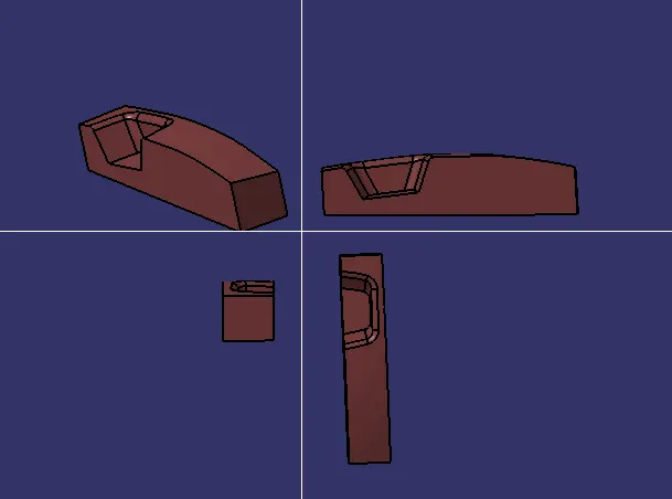
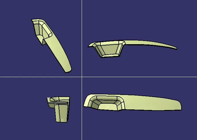
Multi-Section View of Plastic Component:
Draft Analysis on Plastic Component:
1. Change the surface to material mode. Click and drag the compass on the tooling axis. Click anywhere to start the draft analysis. GREEN color shows thst the surface is more then 2.9 degree.
2. BLUE color shows that the surface is less than 0 degree.
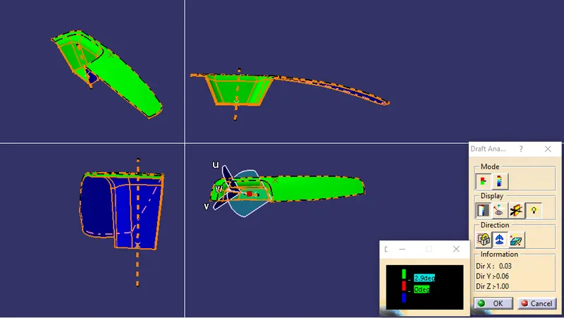
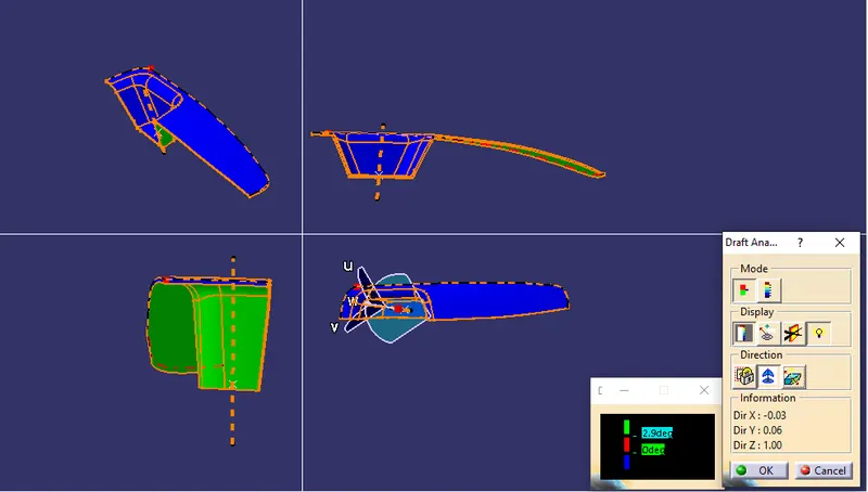
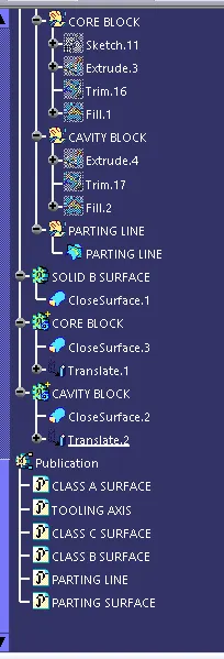
Multi-Section View of Core & Cavity Block:
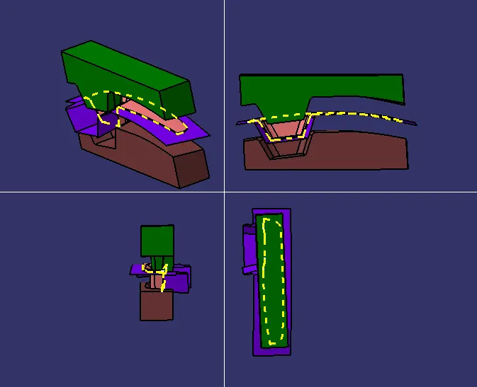
Multi-Section View of Core Block:
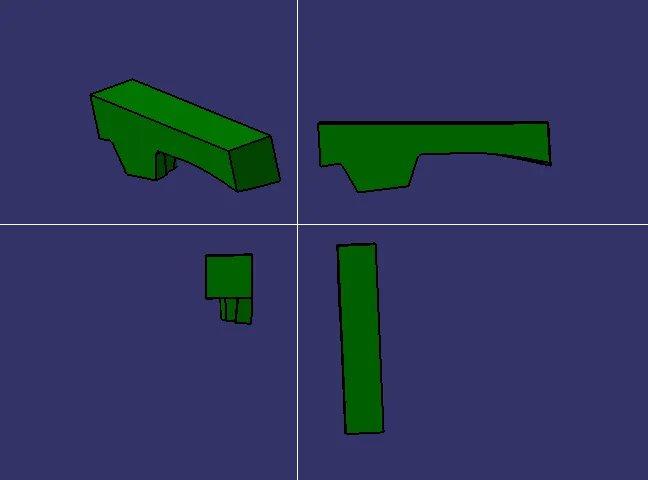
Multi-Section View of Cavity Block: