Week 8 - Challenge 6 - Core & Cavity Design
AIM
Create the Core and cavity blocks for the switch bezel plastic component.
THEORY
CLASS A SURFACE: Class A surface is a surface made by the designer specially in automotive design which is the aesthetic part of a body and is given as an input to the plastic designer to work on it.
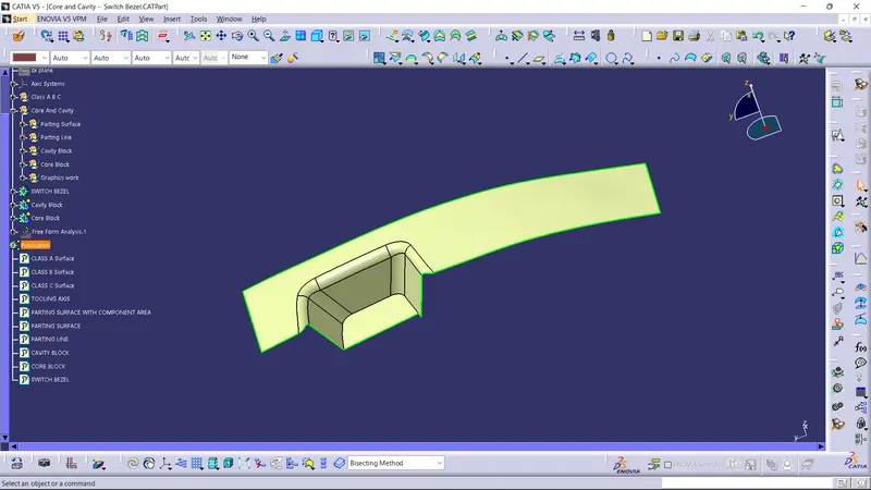
CLASS B SURFACE: It is a surface which comes below the class A surface with a particular thickness. This surface contains engineering features of a model.
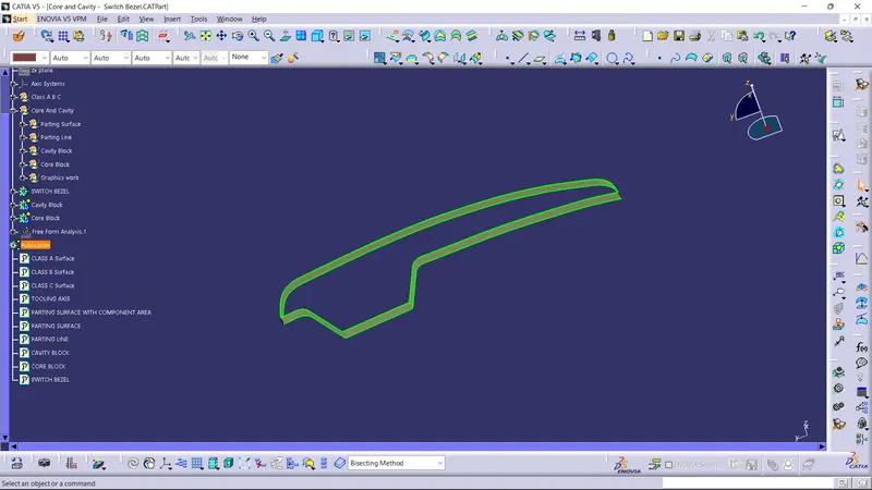
CLASS C SURFACE: It is the surface which joins class A with class b surface.
TOOLING AXIS: Tooling axis is the direction in which the core and cavity opens. If we are using proper tooling axis, we can avoid adding side cores thus the cost of manufacturing the component can be reduced.
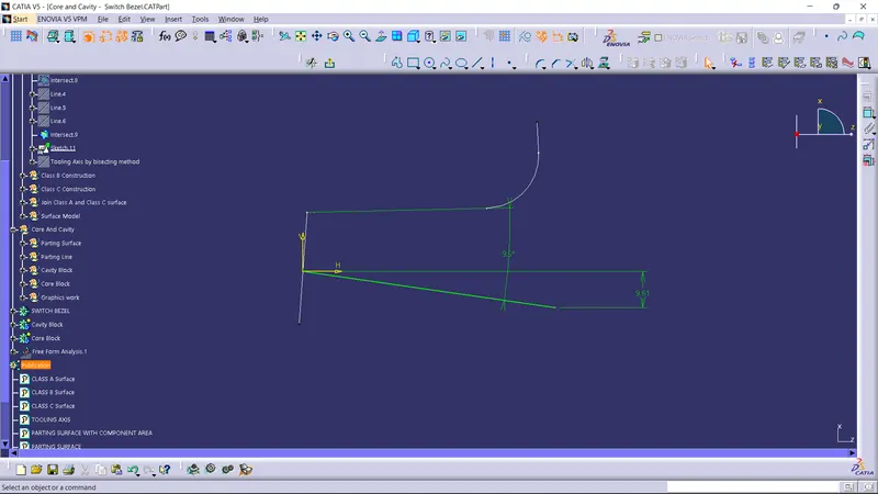
BISECTING METHOD: It is a method used to create tooling axis. Here, the tooling axis is created from other two lines extracted from the class A surface in ZY plane which are inclined and a line is created by selecting bisecting option from the line definition dialogue box. Then another line is created in ZX plane which is given a draft more than 3 degree. Thus, from the above two sketches a bisecting line is created along the point which gives the tooling axis.
Creation of tooling axis using Bisecting method:
Step 1: Rotate the model and finds the surfaces that are inclined and are supposed to affect the tooling axis of a component.
Step 2: By using intersection tool, a curve is obtained from the intersection of the plane we choose and the surface selected. Here, we choose ZY plane and is intersected to get two inclined lines for having tooling axis.
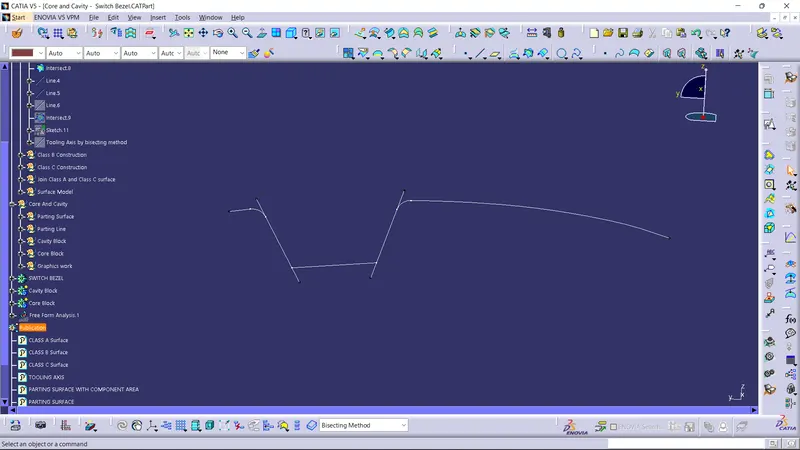
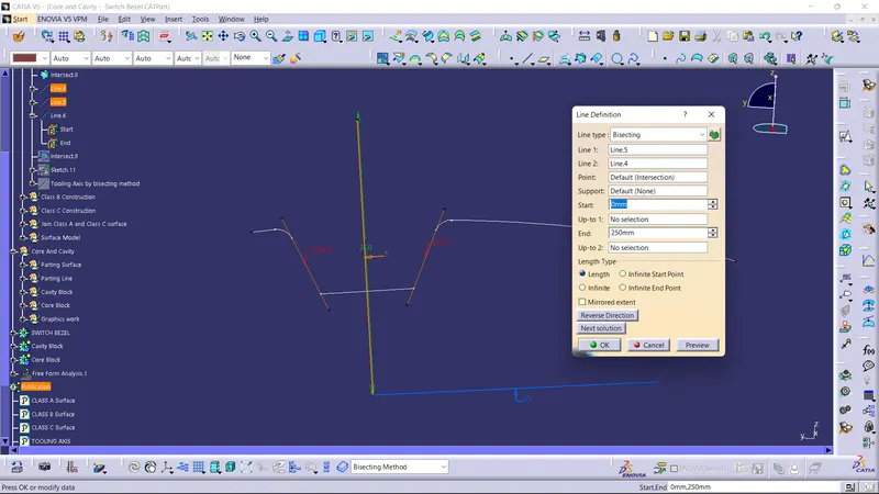
Step 3: Another plane is chosen in switch bezel as there is another inclined plane. So ZX plane is opted and the surface is intersected. A line is drawn and is made to have an angle greater than 3 degrees from that.
Step 4: Bisecting line is drawn from the two inclined lines drawn in different sketches, by opting bisecting from line definition. Thus, tooling axis is obtained.
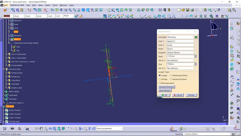
Step 5: From this tooling axis, draft analysis is done to check whether whole surface is clearing or not and thus confirms the tooling axis.
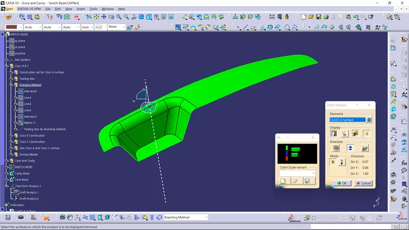
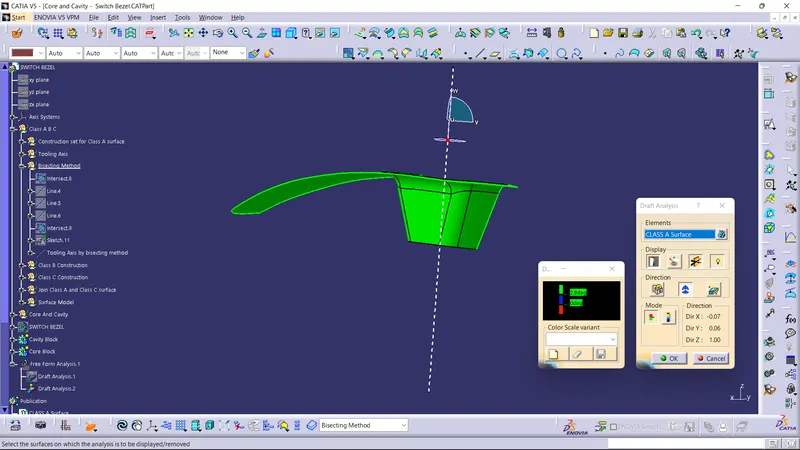
Here, I had used Normal to surface as tooling axis as the tooling axis. Because, Bisecting method is rarely used and not proper method of using tooling axis. Using bisecting method to have tooling axis have many limitations. So, while creating a tooling axis, it is recommended to look for the directions in the axis system to have draft analysis. If those axis system doesn’t clears the draft analysis look for normal to surface to have a tooling axis.
DRAFT ANALYSIS: From draft analysis, we can verify draft angles, examine the angle changes within a face, as well as locate parting lines, injection and ejection surfaces in parts.
Draft analysis in Catia:
Step 1: Ensure that customize view parameter is enabled and material mode is opted in view mode customization.
Step 2: Now go to insert > analysis > feature draft analysis.
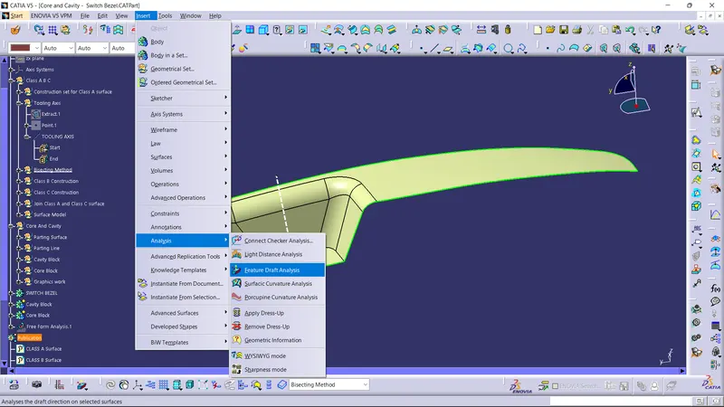
Step 3: Drag axis bar to the tooling direction of part.
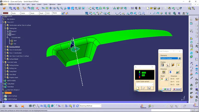
Step 4: Check for draft.
Surface will be in green if the draft angle is more than 3 degrees, blue if draft angle is between 0 to 3 degree and red if draft angle is less than zero degree.
Three degree is the nominal value for draft, whereas 0.5 degree can also be manufactured at ribs.
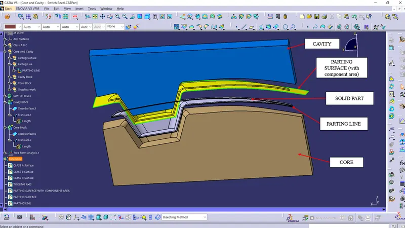
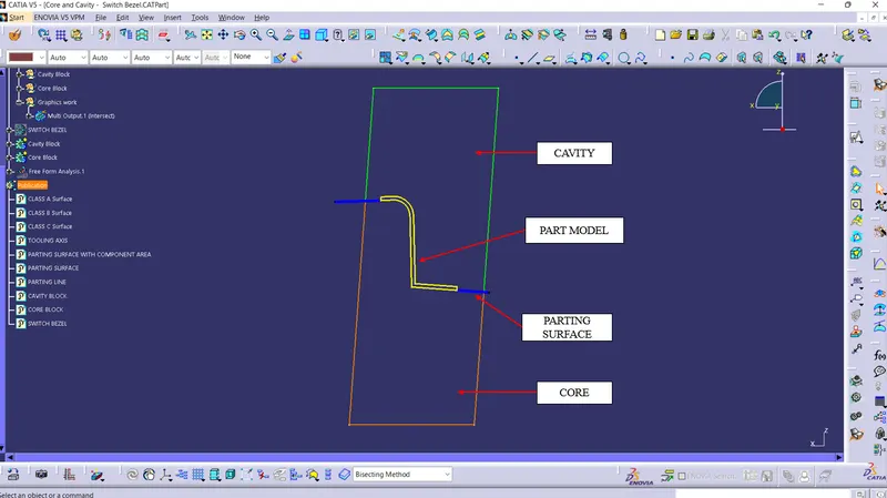
PARTING SURFACE: A parting surface is a surface that separates the mold block into two parts – the core and the cavity. Usually, parting surface are the biggest outline of the part.
PARTING LINE: A parting line, in industrial casting of molds, is the border line in which draft angles change direction. One can check the parting line in the mould or product which divides the two halves, i.e; the core and the cavity of a molded part. It is sometimes a starting point for the mold parting surface.
CORE and CAVITY: Cavity and core are used in the injection molding process, where the concave part of the mold is the cavity and the convex part is the core. The cavity and core are used in pairs, with the cavity also referred to as the female mold and the core as the male mold.
It is not necessary that the core side is always having the projection and cavity having depression. Core is the movable half whereas, cavity is the fixed half. In most of the cases core is with the class B surface as core is having the ejector pins, so if core side with class A surface, it affects the aesthetic property of the part. Cavity will be with the class A surface.
Translated view of the switch model:
Section view of the switch model:
OBJECTIVE
- Creation of Tooling axis.
- Creation of closed surface from provided class A surface.
- Creation of solid part out of surface modelling.
- Draft analysis of Class A surface and final part.
- Creation of parting surface for the part.
- Creation of core and cavity for the solid model.
PROCEDURE
Class A surface is provided as the input. If the surfaces are not joined, then the surfaces should be joined to get Class A surface. The surface is then allowed to publish.
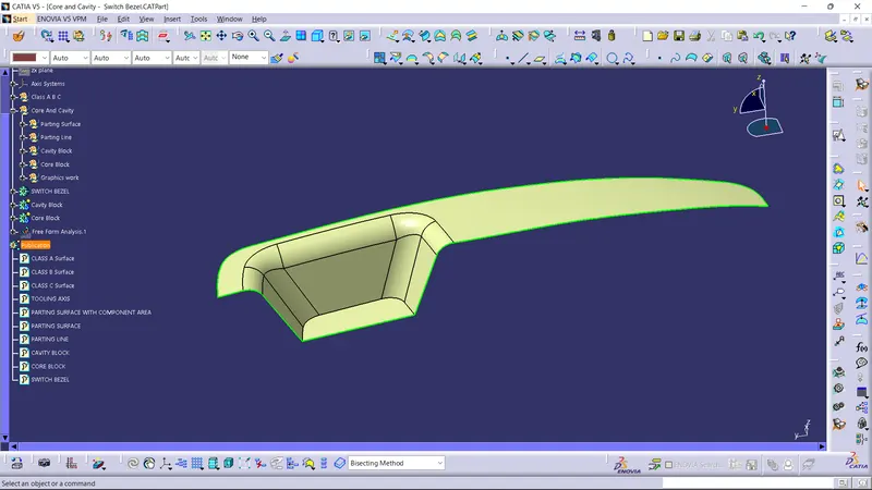
Creation Of Tooling Axis
- Tooling axis can be created using Bisecting method as explained before.
- Here, tooling axis is created as Normal to surface as it is more acceptable form of selecting a tooling axis.
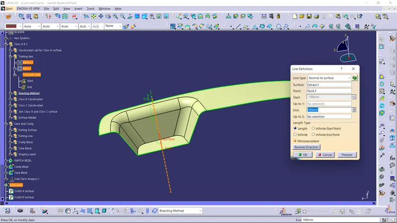
- Tooling axis is created from extracting a flat face and creating a point at its centre
- Now, line is created using line tool and giving line type as normal to surface of the extracted surface and create the tooling axis.
Draft Analysis Of Class A surface
- Draft analysis is performed over Class A surface and every surface is obtained as clearing.
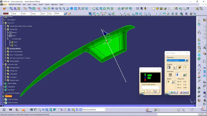
After draft analysis, Class B and Class C surfaces are created. Then, Class A surface is joined with class C surface. The obtained surface is then trimmed with Class B surface and a closed surface is then obtained.
Class B surface:
Class C surface:
Closed Surface:
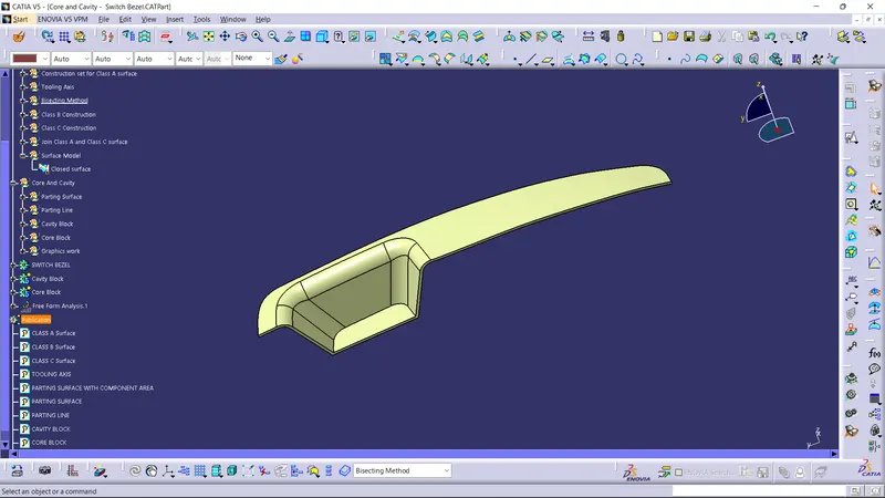
Solid Part:
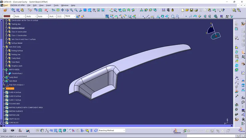
Creation Of Parting Surface
- Class B and Class C surfaces are trimmed and is joined with extrapolated class A surface to obtain a parting surface with component area.
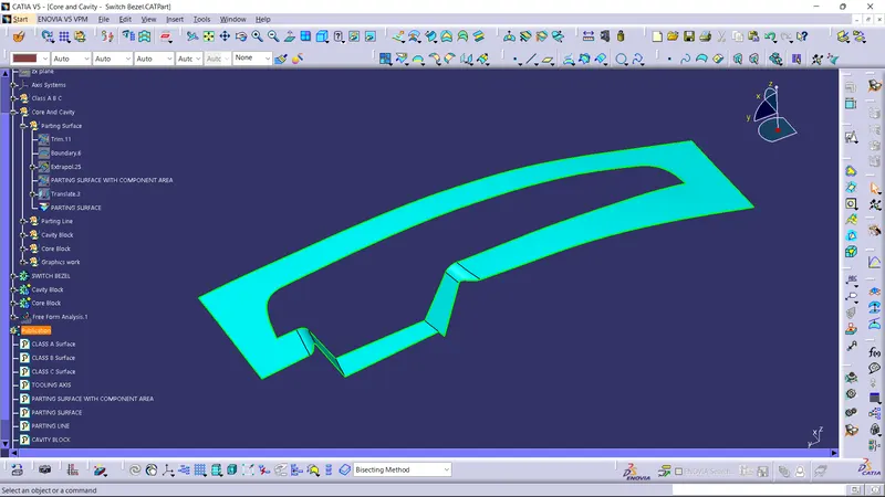
- If the obtained surface is splitted using the parting line, parting surface is obtained.
Parting surface with component area:
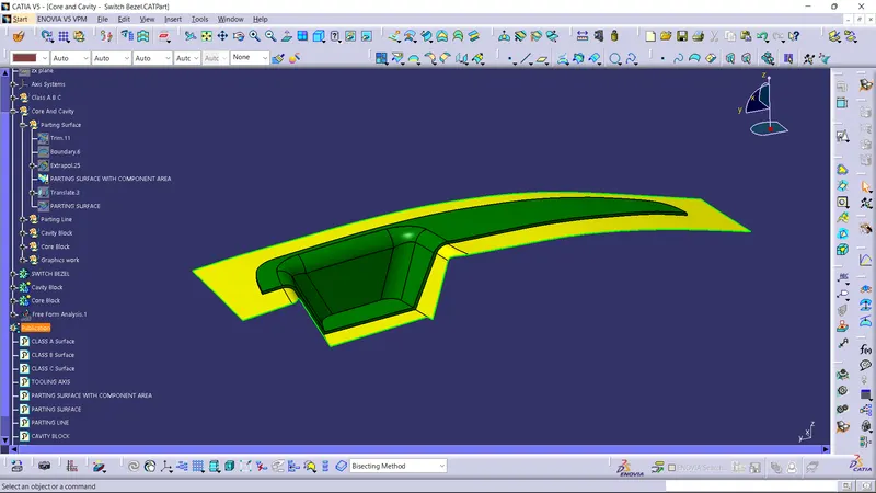
Parting surface:
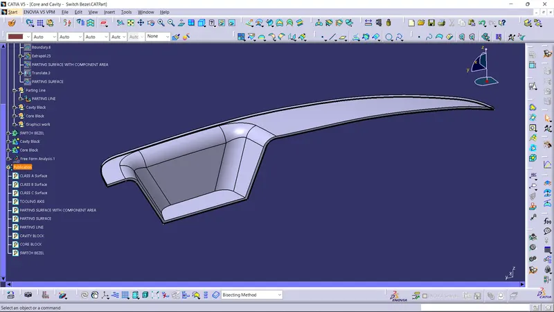
Creation Of Parting Line
- Parting line is created using multiple extract from the part model or parting surface can also be obtained by intersecting the joined class A and C surface with class B surface.
Creation Of Cavity Block
- Cavity block created by initially drawing a rectangle which is to be extruded so as to make it able to trim with parting surface with component area. Thus, a box is obtained which is the cavity block.
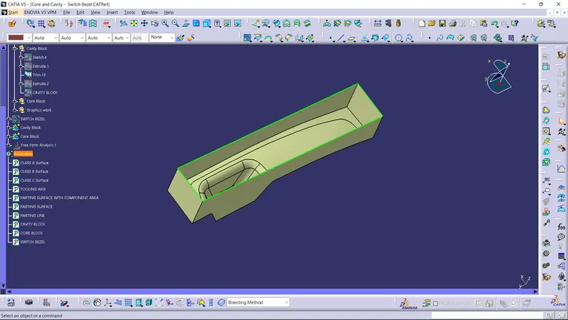
Screenshots Of The Cavity Block In Various Orientations:
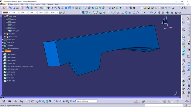
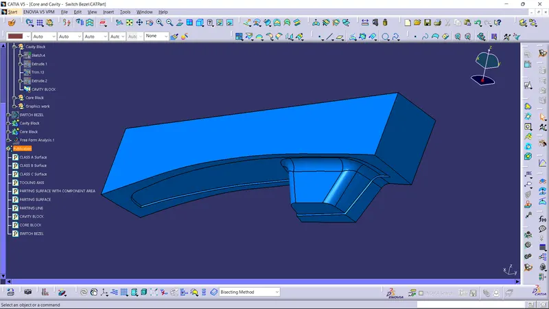
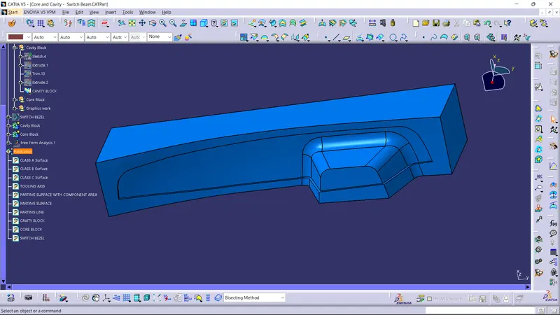
Creation Of Core Block
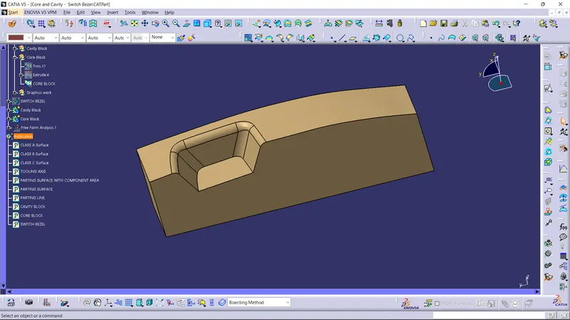
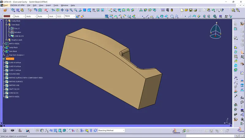
- Core block is obtained by trimming class B surface with the previously extruded surface. Thus, obtained below block is the core block.
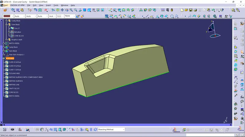
Screenshots Of The Core Block In Various Orientations
CONCLUSION
- Created Tooling axis.
- Created Class B and Class C surface from provided Class A surface.
- Created solid part out of surface modelling.
- Draft analysis of Class A surface and final part is also done.
- Created parting surface for the part.
- Created core and cavity for the solid model.
REMARK: I'm using latest version of Catia. So, I had done a one on one session with the Technical Support Engineer on 16th July.