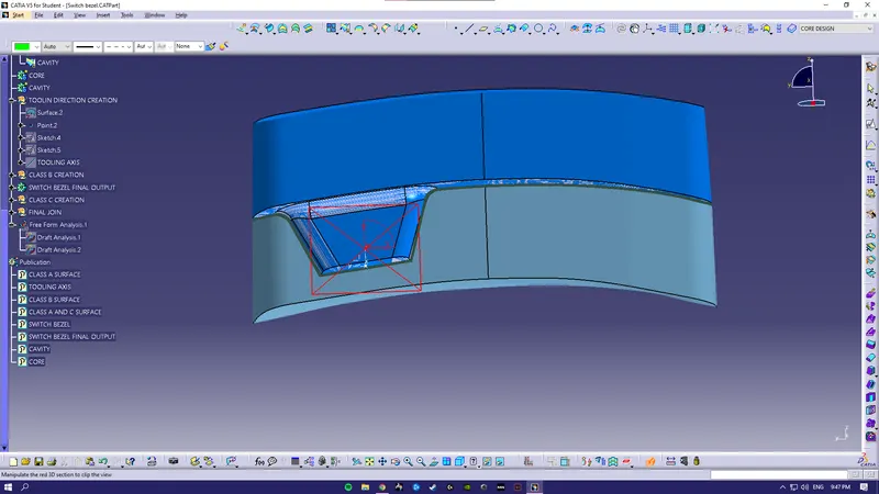
Week 8 - Challenge 6 - Core & Cavity Design
AIM:
To Create the Core and cavity blocks for the switch bezel component.
CREATING TOOLING AXIS -
The Tooling Direction is basically the direction that the mold pulls a part. The mold is built in two separate pieces, basically. You have a Cavity side and you have the Core side. The Core pulls apart from the Cavity and that's the Dye line or the Tooling Direction.
BISECTING METHOD:
Bisecting method is basically use to find the proper tooling axis using the dummy tooling axis. In Bisecting method, bisecting line is used which either bisect the two line or it will show error which means the two lines are parallel to each other. In order to know whether the particular surface is toolable or not we intersect the surface with the respective plane and get a sketch which consist of two lines and with the help of bisecting line option we bisect the line which creates a line at the mid point of the two lines. Like wise we create tooling clearing axis for x and y which will be used to create the main tooling axis using the bisecting line option in in the line comand.
- Intersect the yz plane with respect to the class A surface.
- Hide the class A surface and create point to point lines on the suspected drafts.
- Create bisecting line with the two lines and point to create a tooling axis.
- BISECTING LINES were used to get the exact medium from the two sides so that maximum positive draft angle can be achieved.
DRAFT
Draft angle is nothing but providing some tapered portion to the part for easy removal of the component from the mold during manufacturing. This is especially done in the case of plastic component design having a complex shape. Mostly the 3-degree draft angle is provided but it can vary depending upon the component which is to be designed
In our case of Switch Bezel design, the draft angle is 3 degrees the draft analysis is done during the design of the component to check the feasibility of the product.
Before providing a draft angle we need to decide on the tooling axis also known as the molding axis considering the faces which can cause issues while manufacturing.
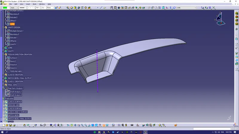
PARTING SURFACE
Generally injection mold has two major components : the movable half and the fixed half, during the injecction molding process, these two halves are pressed tightly from a sealed hollow to avoid the melt flow leakage and maintain certain holding pressure, the pressed surface are called
PARTING LINE
A parting line is an inevitable part of injection molded products.It is the line of separation between where two halves of a mold meet.It manifests itself on injection molded parts as a line that runs the entire perimeter of the part.In most parts, it is just a line that runs straight down the middle.
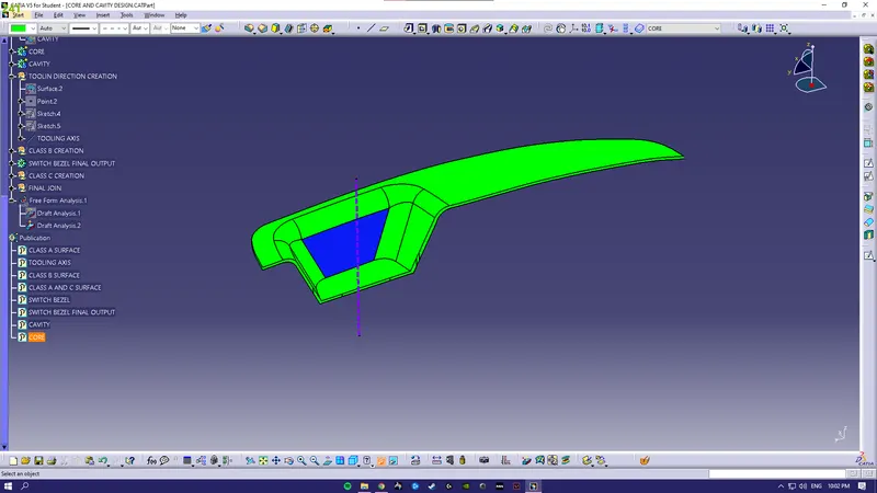
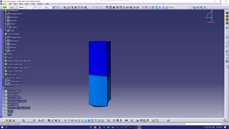
CORE DESIGN
Core - A portion of the mold that goes inside a cavity to form the interior of a hollow part.
Core-cavity - A term used to describe a mold created by mating A-side and B-side mold halves.
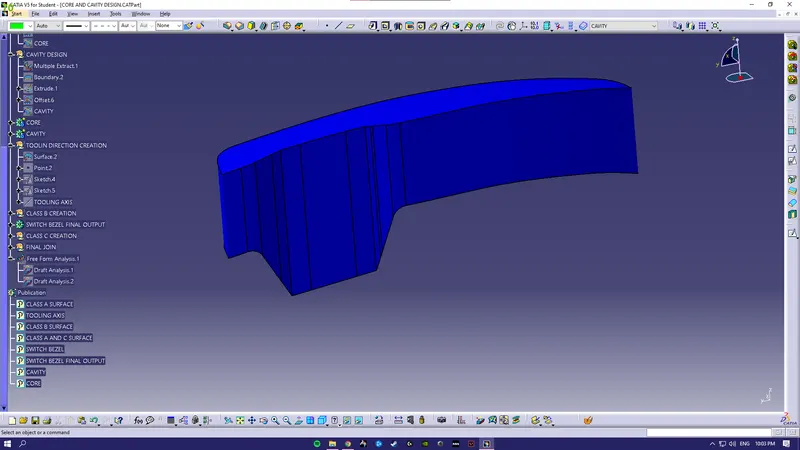
CAVITY DESIGN
A mold is a hollow form typically made from stainless steel that has plastic injected into it to manufacture a plastic part.
The plastic is inserted into the mold cavity, which is a hole in the mold shaped like the desired part.
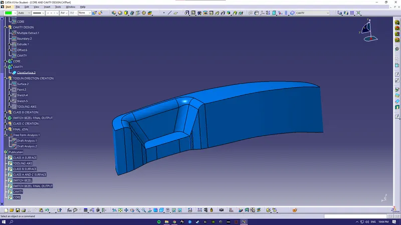
DIFFERENT VIEWS
ISOMETRIC
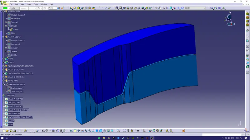
FRONT
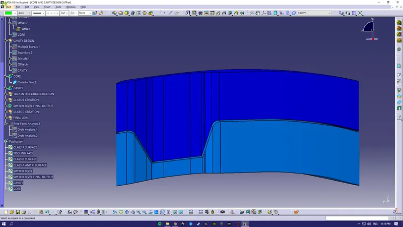
TOP
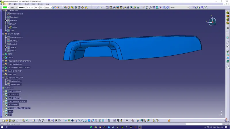
SIDE
CUT-SECTION VIEW