Week 8 - Challenge 6 - Core & Cavity Design
PROJECT
CORE AND CAVITY DESIGN FOR SWITCH BEZEL
Aim:
To create a switch bezel from the given A-class surface by considering a thickness of 2.5 mm and also creating Core and Cavity blocks for it.
REPORT:
CORE AND CAVITY DESIGN FOR SWITCH BEZEL:
Class A Surface:
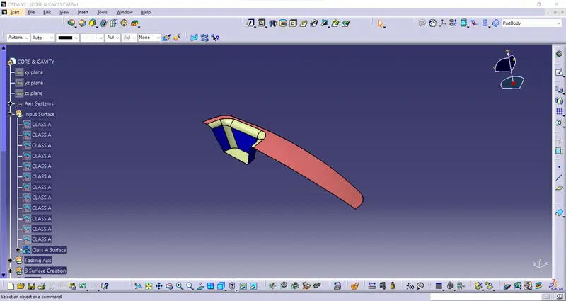
- To start the design process we need to find out the tooling axis for the surface and check the drafts using the Draft Analysis tool in CATIA.
- And Publicize the A surface.
Tooling Axis:
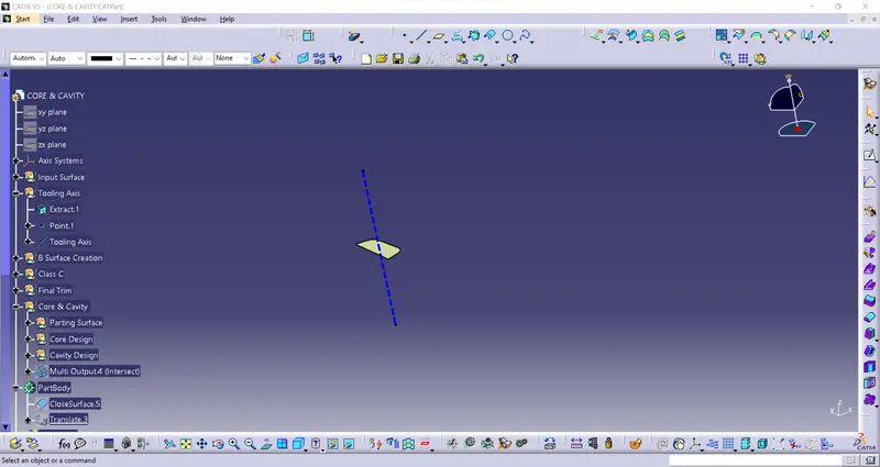
- Create an Extract on a flat surface and point on surface 0mm and Create a Line - NormalTo Surface click on the point and take an Extract , give some color and make it a dashed line.
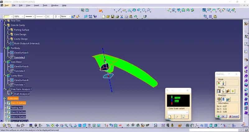
- Take a draft analysis with A surface in positive green and blue, little deviation is there.
- And same thing to do in final draft analysis with final solid component, it seems a deviation green and blue that’s fine acceptable.
- And Publicate the Tooling Axis.
Class B Surface:
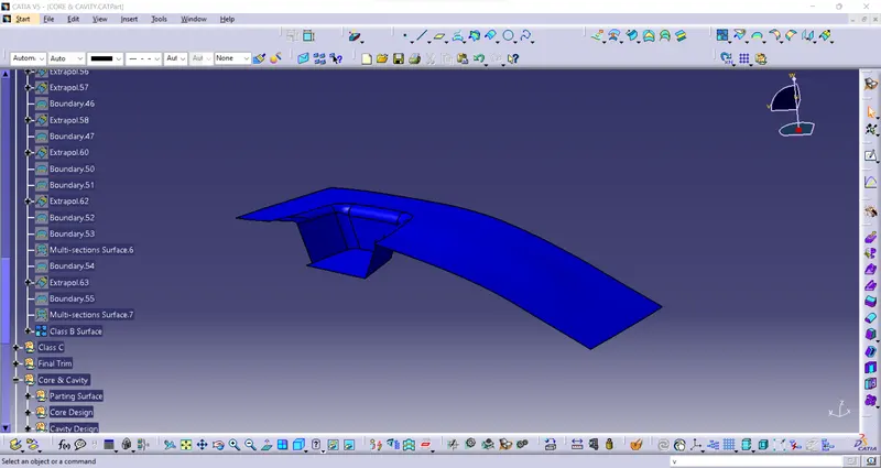
- Take a 2.5mm Offset from Class A Surface upward Downwards the unfinished surface we get .
- Untrim the offseted surface and extrapolate to trim it, get the Class B Surface.
- Then Publicize the B-Surface.
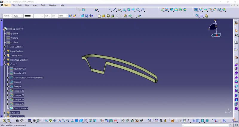
Class C Surface:
- Unhide the A Surface to Take a boundary as a reference to make C surface.
- Go to sweep line-> with Reference with draft direction 3 degree draft angle for all sweep.
- And join all the sweep parts to make a Class C surface.
- Then Publicize it.
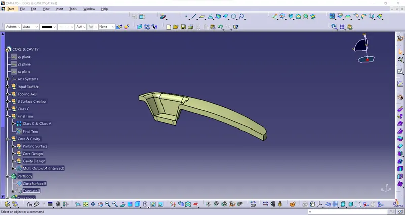
Class C & Class A Surfaces:
- Join the both finished Class C and Class A surfaces.
- Then Publicize it.
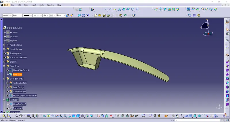
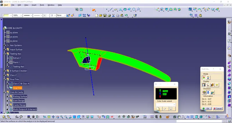
Final trim:
- Take a Joined part C Surface And A Surface to Trim with Class B Surface, we get the output closed surface body.
- Then Analyze the Draft with the final part.
- Publicize it.
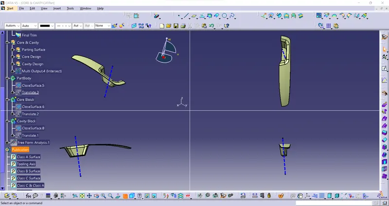
Core & Cavity:
- The Mold Core & Cavity are the shaped sections in either half of the mold tool which give the plastic product its final shape.
- The hot molten material is injected into the core & cavity and then sets hard into shape. The design of the core & cavity is essential in the correct formation of the product. The sequence of events during the injection mold of a plastic part is called the injection molding cycle.
- The cycle begins when the mold closes, followed by the injection of the polymer into the mold cavity.
- A core is usually made of the best quality sand and is placed into the desired position in the mold cavity. Core prints are added to both sides of the pattern to create impressions that allow the core to be supported and held at both ends.
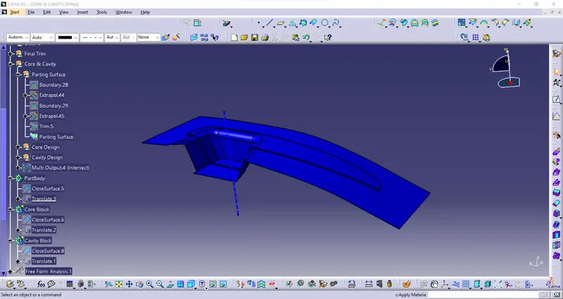
Parting surface:
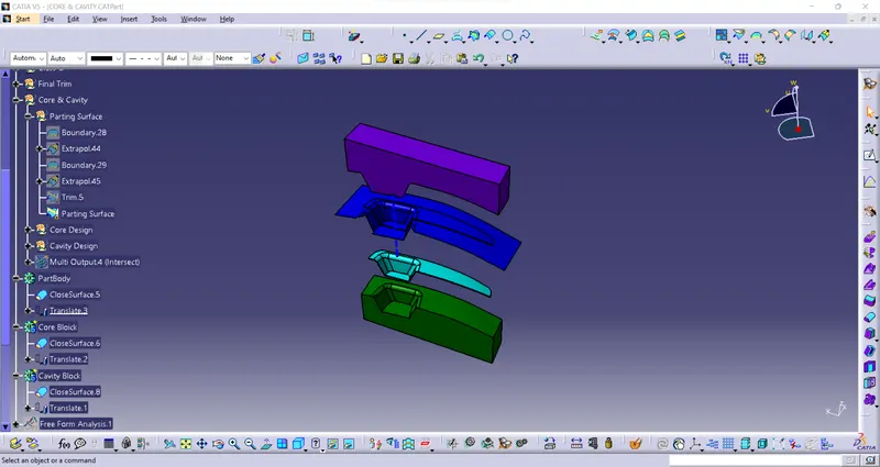
- Unhide the Class A Surface extrapolate it, Trim with C surface and again using trim commant with B Surface To make a parting Surface.
- Then Publicize it.
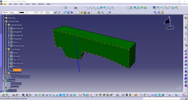
Core Design:
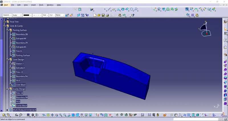
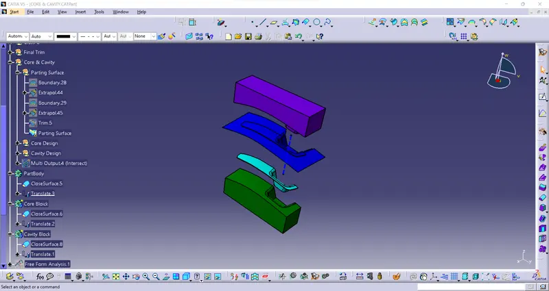
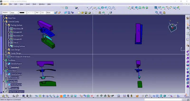
- Create a Sketch on the Parting Surface and Trim it and use fill command to fill it after joining both to make a Core Block or Closed Body.
- Then publicize it.
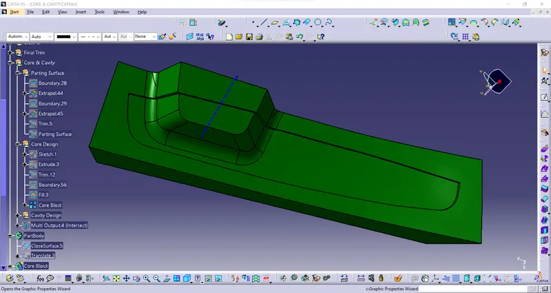
Cavity Design:
- The same procedure of the core block to make a cavity block seems to make little difference in it and the Solid body made.
- Then publicize it.
Conclusion:
The report of “CORE AND CAVITY DESIGN FOR SWITCH BEZEL” Have been successfully Done By Myself and thank you!.