Radar Mast & Final Assembly of Yacht
1.Radar Mast:
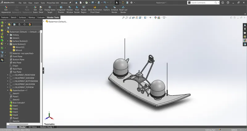
Isometric View:
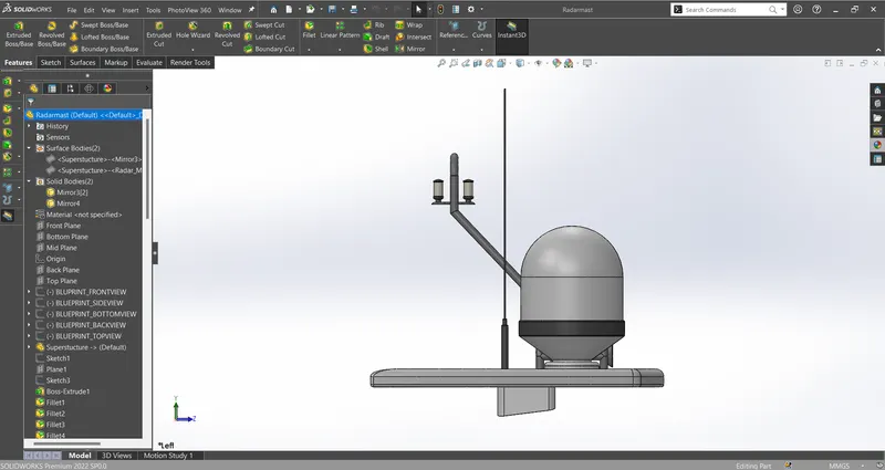
LeftSide View:
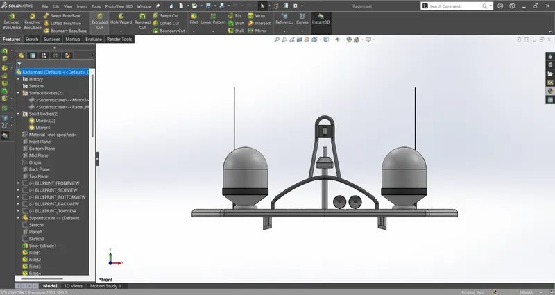
Front View:
Feature Tree 1:
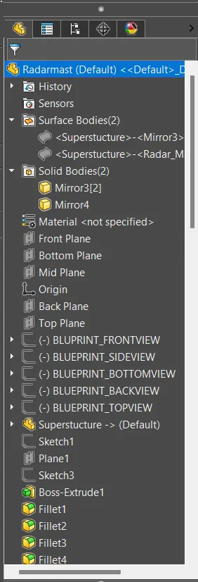
Feature Tree 2:
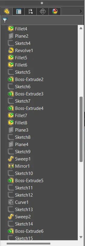
Feature Tree 3:
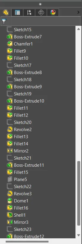
Feature Tree 4:
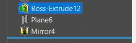
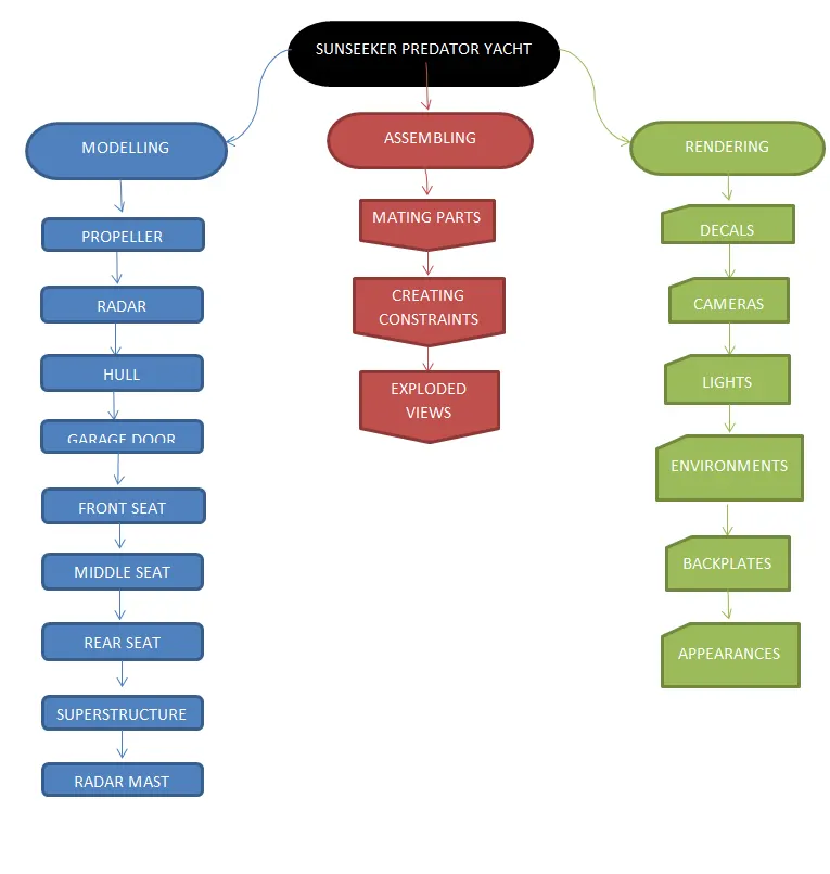
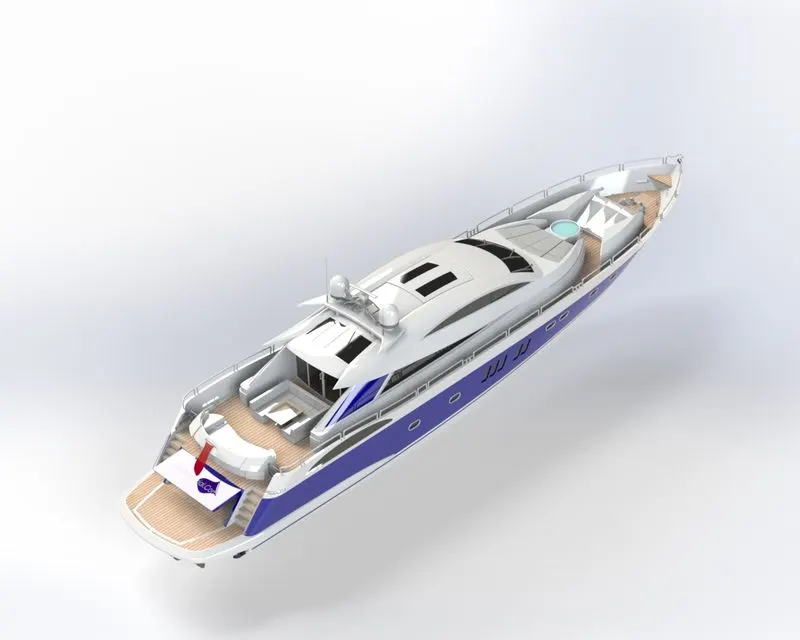
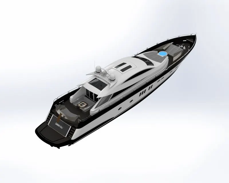
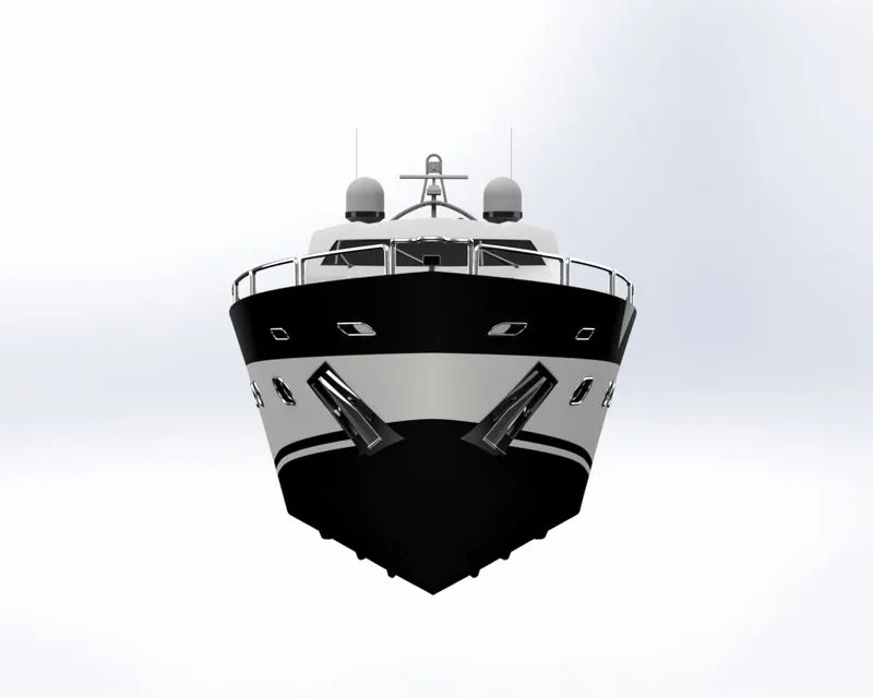
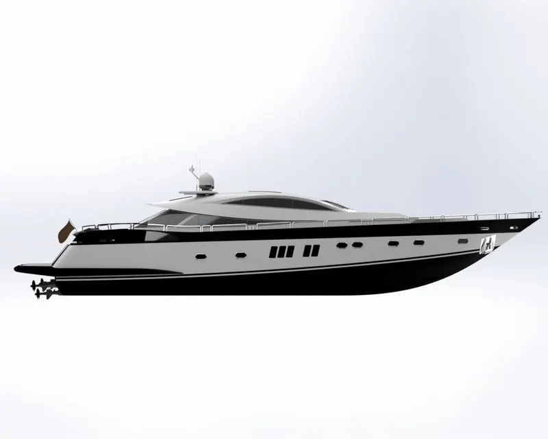
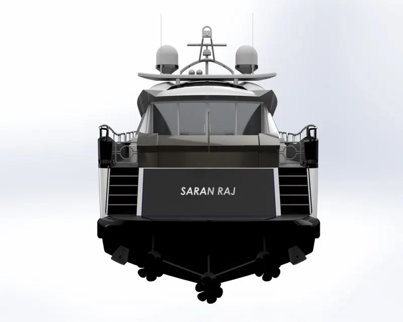
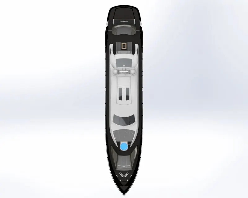
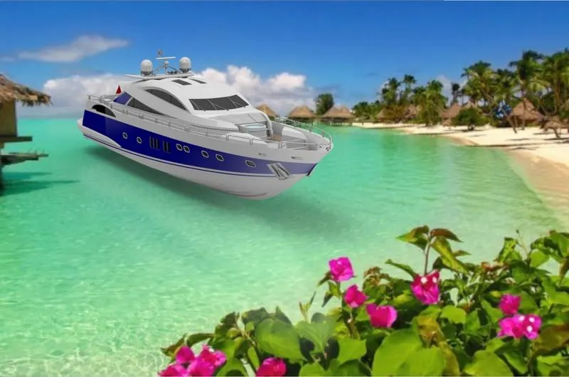
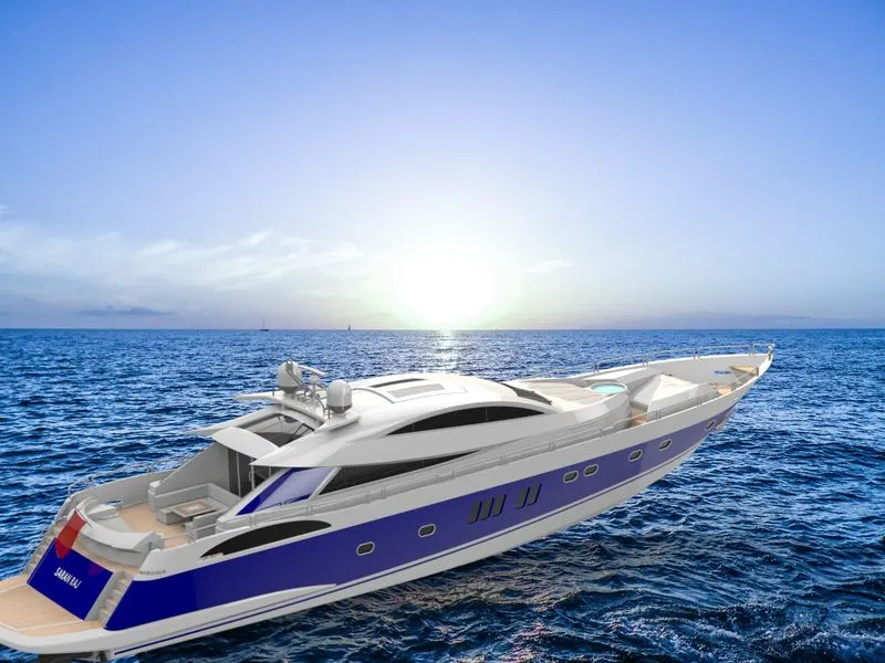
Design, Assembly and Photorealistic Rendering SUNSEEKER PREDATOR YACHT.
Objectives:
Here, I'm Explaining below the SUNSEEKER PREDATOR YACHT Design Project. To Create a Design, assembly of YACHT Using SOLIDWORKS and Photorealistic Rendering YACHT by SOLIDWORKS VISUALIZE.
Introduction:
- Hello all, I'm Excited to Introduce the Project I Designed, SUNSEEKER PREDATOR YACHT, Using SOLIDWORKS. It's a Little bit tough, and Interested to learn the Surface modeling; in This Project 3D modeling methodology of Surface modeling and Solid Modeling Technics.
- Every Part Makes Constrained properly, and The Assembled parts are Proper mates and constraints.
- A yacht is a craft used for pleasure and sport. The name comes from the Dutch word (jaght), which translates as 'hunter,' a fast, light sailing vessel used by the nation's navy to chase pirates and other ne'er do wells.
- The SOLIDWORKS CAD Software is a Mechanical Design Automation Let That lets designers quickly sketch out ideas, experiment with features and dimensions and produce models and detailed drawings.
- Photo View 360 is a SOLIDWORKS add-in that produces photo-realistic renderings of SOLIDWORKS models. The rendered image incorporates the appearances, lighting, scene, and decals included with the model.
- SOLIDWORKS Visualize allows you to leverage your 3D CAD data to create photo-quality content in the fastest and easiest way–from images to animations, interactive web content, and immersive Virtual Reality.
Design Approach:
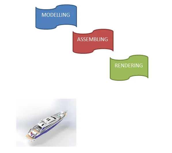
Design Methodology:
Types Of Comands:
Sketch: Create sketches and decide how to dimension and where to apply relations.
Features: Select the appropriate features such as extrudes and fillets, determine the best features to apply, and decide how to use these features.
Surfaces: Surfaces are a type of geometry that can create stable features.
Assembly: Select the components to mate and apply the mates.
Sketch:
To create 2D drawings with fully defined constraints, sketch to make a 3D model. You can create a sketch on any default plane (Front Plane, Top Plane, and Right Plane) or a designed aircraft. You can start by selecting: Sketch entity tools (line, circle, and so on).
3D Sketch:
- When sketching in3D, we can snap to the significant directions, X, Y, Z, and constraints are applied along X, Y, and Z, respectively. These are constraints to the global coordinate system.
- When sketching on a plane, we can snap to the horizontal or vertical directions in the plane, and constraints are applied to the horizontal and the vertical. These are constraints to a plane, plane face, face.
Part Modelling:
Part modeling is creating a virtual prototype of something by modeling each part separately, which can then all be assembled to create the model of the final product.
Surface Modelling:
Surface modeling is an alternative to solid-body modeling. Essentially, it's just another tab at the top of the SOLIDWORKS User Interface. Surface modeling is an essential tool in your box because it makes modeling more accessible and sometimes makes modeling possible.
Sketch Commands:
Smart Dimensions: Create dimensions for a selected sketch entity.
Line: The line is one of the first sketching tools in SolidWorks sketch command manager, which can be drawn horizontally, vertically, or at an angle. It plays a vital role in completing the 2D drawings of the product or part and is very easy to utilize its feature.
Circle: The circle is another important sketching tool that enables to create the circular drawing on the graphics area. There are two circle tools available: the "center circle and Perimeter circle."
Rectangle: Sketches rectangles or squares with a center point at a selected angle. Parallelogram sketches a standard parallelogram.
Spline: A 2 or 3-dimensional curve is defined by control points. Points within a spline can be added or deleted.
Sketch fillet: A tangent arc between two sketch entities can be created.
Point: Insert a Point or vertex into a sketch entity. This cannot be deleted if it is part of the sketch endpoint or center point.
Text: It can be used to write the text necessary wherever required, whether it's a plane or face.
Offset entities: Copy a Sketch entity to a specified distance from the original entity. Must have a sketch entity already drawn and selected to use this tool.
Sketch Picture: Insert an image file into the background of a sketch. This allows the user to do 2D drawings based on the image. Use the sketch picture property manager to alter the inserted image.
Convert Entities: Convert entities enable you to copy model edges into your active sketch. These sketch elements are automatically fully defined and constrained with an on-edge relation. Convert entities are like offset entities, except the offset distance is always zero.
SURFACE COMMANDS AND FEATURE COMMANDS USED IN THIS SUNSEEKER PREDATOR YACHT PROJECT:
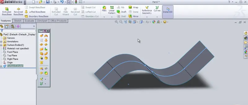
Surface Extrude:
Extrude a Sketch or Sketch contours in one or two directions to create a surface feature. You can control where the to extrude starts from and define its movement and extension.
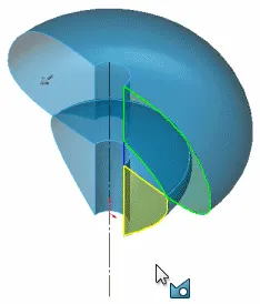
Surface Revolve:
Revolves a sketch or selected sketch contours around an axis to create surface features.
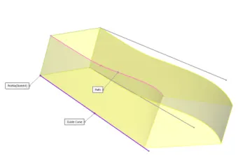
Swept Surface:
Sweeps a closed profile along an open or closed path to creating a surface feature. You can use guide curves, profile orientations, and twist angles to create different shapes.
Lofted Surface:
Creates a lofted surface between two or more profiles or sketches. Specify start and end constraints and add guide curves to control the path shape.
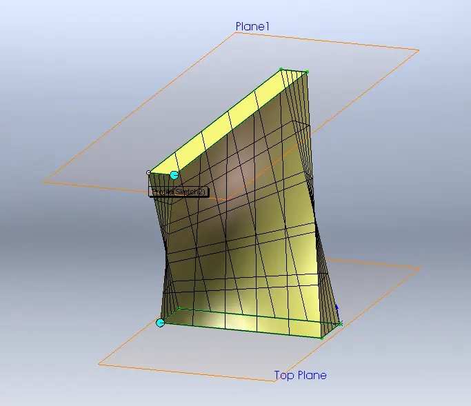
Filled Surface:
Patches a surface within a boundary defined by edges, sketches, or curves. Use constraints curves to surface fills and adjust resolution control to improve surface finish.
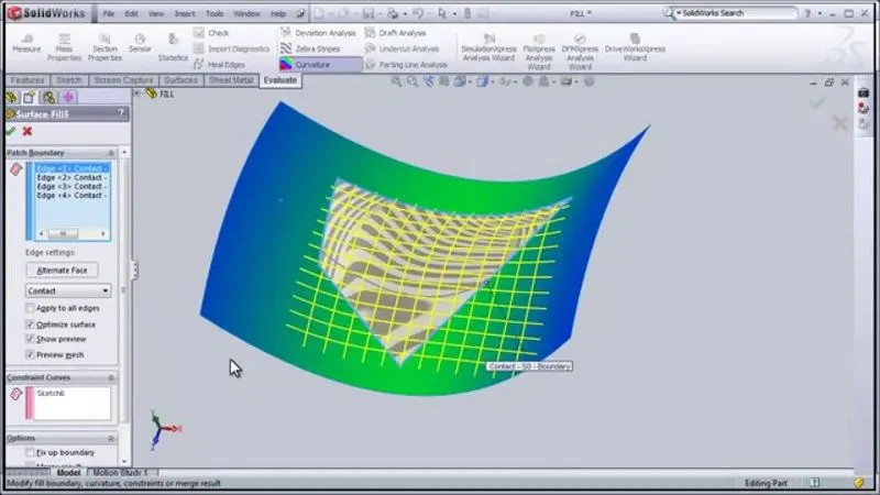
Offset Surface:
Using one or more contiguous faces. The tool creates an offset surface with gaps. You can repair the gaps manually or adjust the offset distance value and rerun the tool.
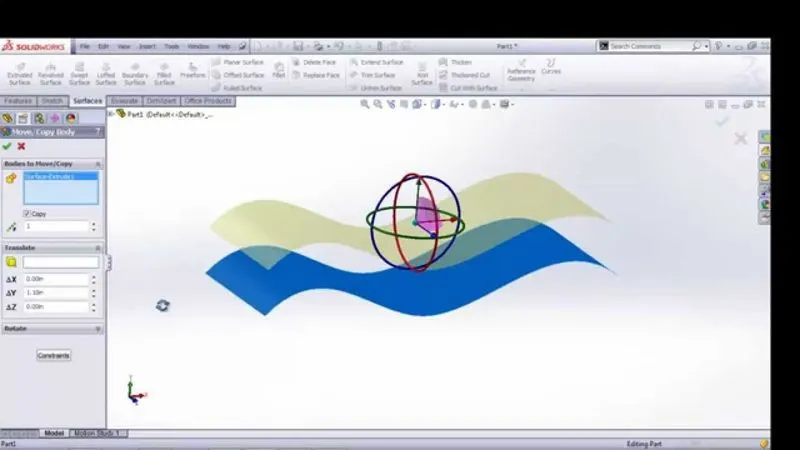
Ruled Surface:
Inserts ruled surfaces in a specified direction from edges. You can trim and knit the covers and remove connecting characters.
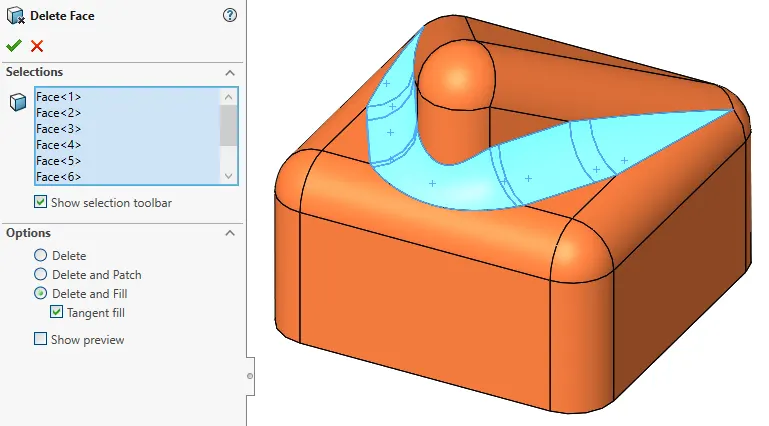
Delete Face:
Delete faces from solid bodies to create a surface or delete a look from a surface body. You can also delete and patch faces to form continuous characters or delete and fill to replace faces with a single face.
Extend Surface:
Extends one or more edges or faces on a surface, based on end conditions and extension type.
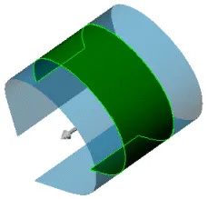
Trim Surface:
Trims Where a Surface Intersects with another surface, a plane or a sketch. Select a trim type, small tool and the characters to keep or remove.
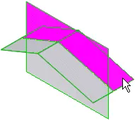
Knit Surface:
Combines two or more adjacent, nonintersecting surfaces into a single surface body. The characters must join at an edge. If the resulting knit cover encloses a volume, you can create a solid body from the property manager.
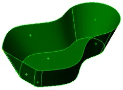
Thicken:
Create a Solid Feature by thickening one or more adjacent surfaces. Adjacent surfaces must first be knit.
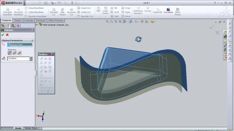
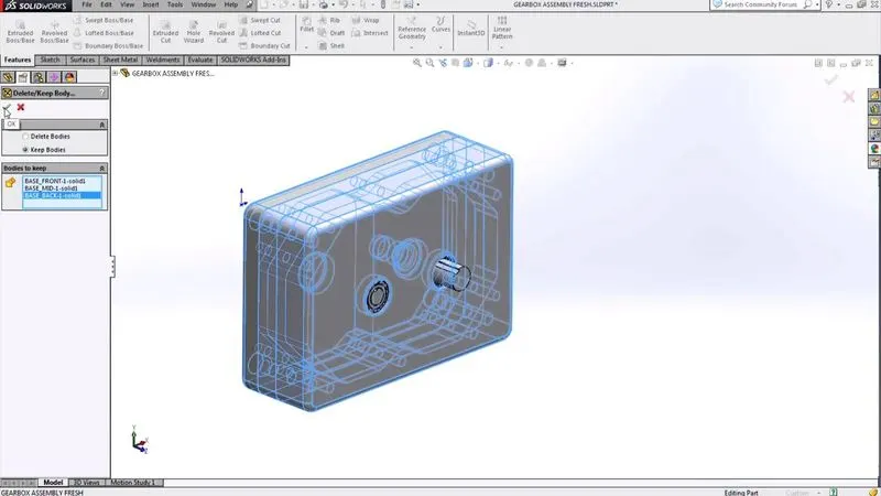
Delete/Keep Body:
Delete or keep one or more solid or surface bodies.
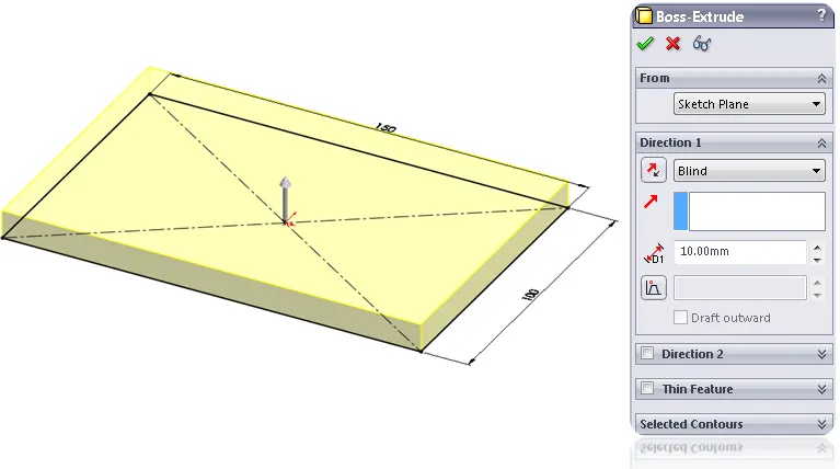
Extruded Boss/Base:
Extrudes a sketch or selected contours in one or more directions to create a solid feature.
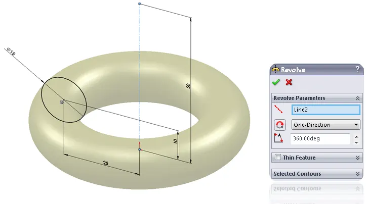
Revolved Boss/Base:
Revolves a sketch or selected sketch contours around an axis to create a solid feature.
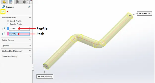
Swept Boss/Base:
Sweeps a closed profile along an open or closed path to creating a solid feature.
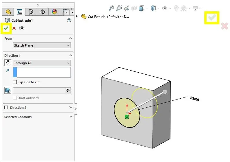
Extruded Cut:
Cut a solid model by extruding a sketched profile in one or two directions.
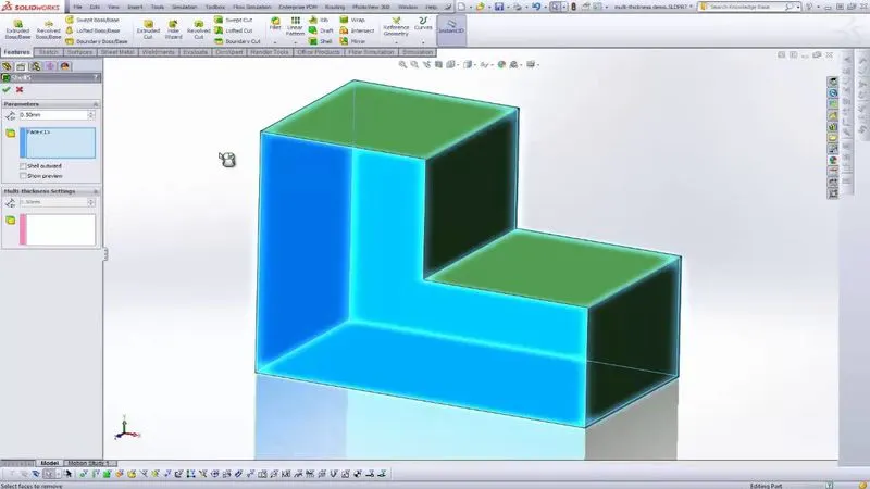
Shell:
Hollows out a part, leaving the faces you select open and creating thin-walled features on the remaining faces.
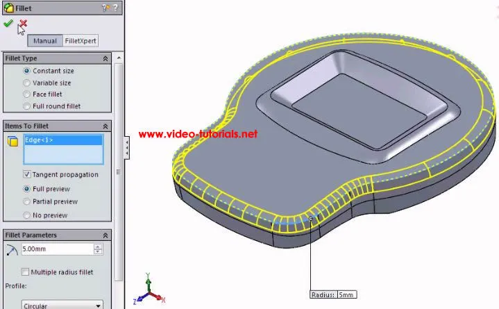
Fillet:
Creates rounded internal or external faces along one or more edges on a solid or surface feature. Fillet can be of constant or variable size.
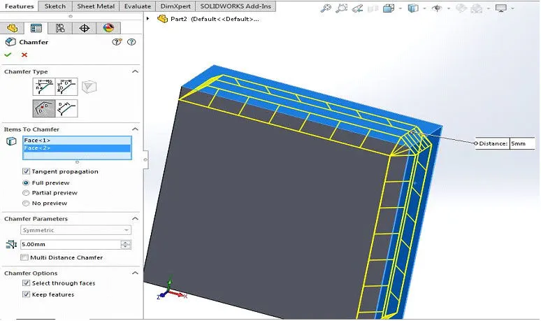
Chamfer:
Create a bevel feature along an edge, a chain of tangent edges, or a vertex.
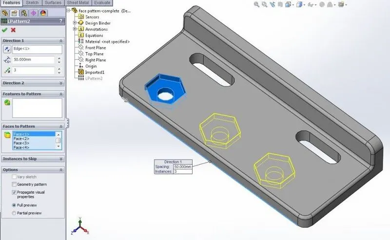
Linear Pattern:
Patterns features, faces and bodies in one or two linear directions.
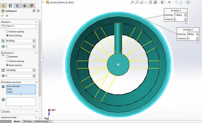
Circular Pattern:
Patterns Features, faces, bodies around an axis.
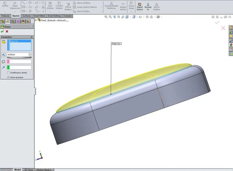
Dome:
Adds one or more domes to selected planar or non-planar faces.
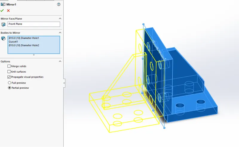
Mirror:
Mirror Features, Faces, and bodies about a face or a plane.
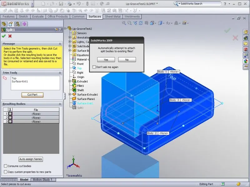
Split:
Creates Multiple bodies from a single body. You can Create the bodies in the existing part or separate parts.
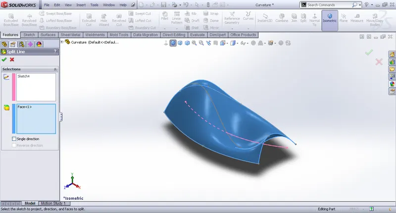
Split Line:
Projects a sketch to curved or planar faces, Creating multiple separate looks.
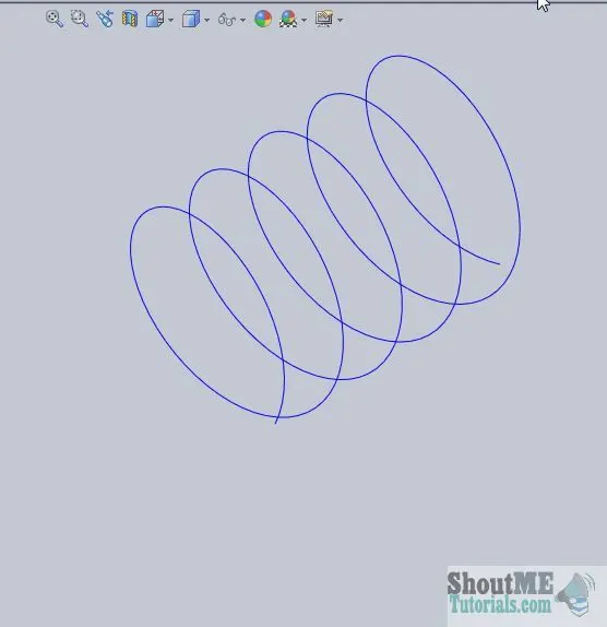
Helix and Spiral:
Adds a helix or spiral curve from a sketch circle.
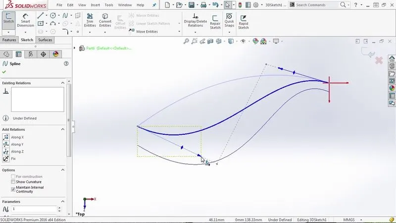
Projection Curve:
Projects a sketched curve onto a face or sketch.
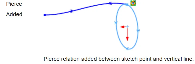
Pierce Relationship:
The pierce relationship is used in sweeps. It can be thought of like a 3D coincident relationship. In our spring, the circle will follow the helix. Think of the helix as a thin piece of wire and the profile sketch as being drawn on paper. The paper will slide along the wire when we perform the sweep, held at the pierce point. If we stick the wire through the form at the circle's center, this would be a pierce relationship.
Part Modelling:
- Propeller
- Radar
- Hull
- Garage Door.
- Front Seat.
- Middle Seat.
- Rear Seat.
- Superstucture.
- Radar mast.
BluePrint:
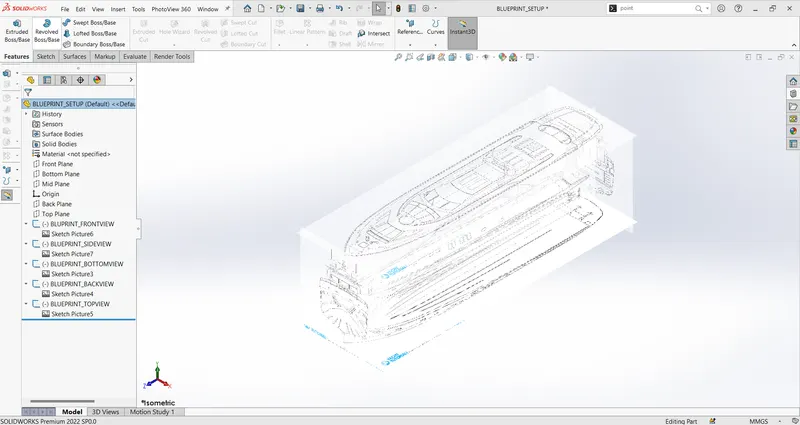
- It is a design or a technical drawing that explains the component's overall details. We communicate, understand specifications and design the blueprint. It's a softcopy of imagining the values of the project. It can be used to understand and explain the detailed work plan with the help of design mode.
- The figure below is the Blueprint of the Sunseeker predator yacht that is fully defined constraints. The sketch picture options were used to set up the blueprint and placed the different blueprints at the required planes.
Propeller:
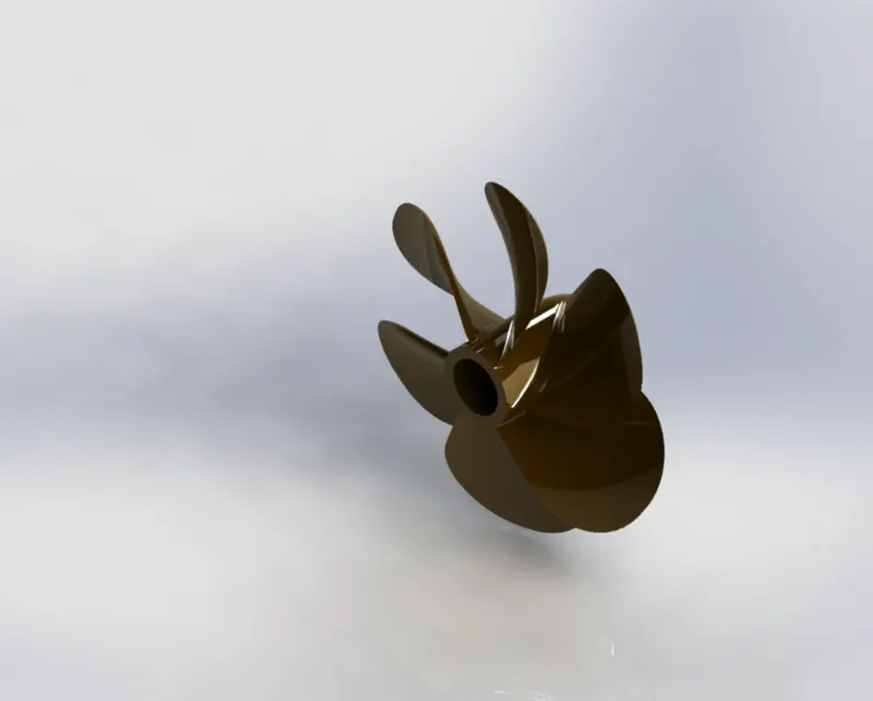
- A propeller is a rotating fan-like structure used to propel the ship by using the power generated and transmitted by the ship's main engine.
- There can be one, two, or three propellers. It is the essential part of the ship without which a boat can't move. So, the primary function of the propeller is to propel the ship in the forward direction by producing thrust on water. Its working principles are newton's third law of motion and Bernoulli's theorem.
Command used to model:
In Sketch
- Spline
- Circle
- Line
In Feature
- Revolved Boss/Base
- Lofted Boss/Base
- Extruded Cut
- Reference Plane
- Circular Pattern
- Fillet
Radar:
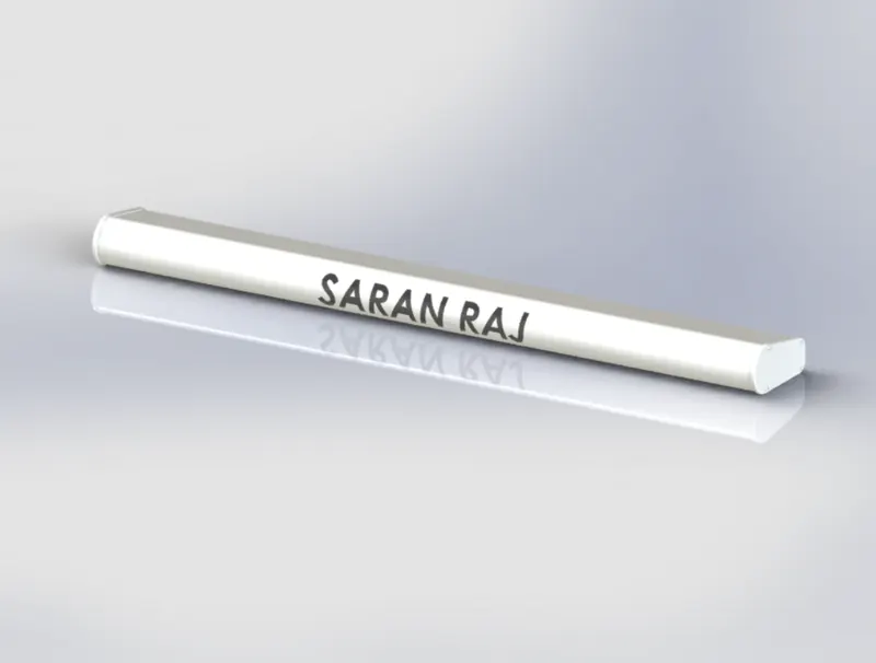
- Radar is a vital navigation component for safety at sea and near the shore. Captains need to be able to maneuver their ships within feet in the worst of conditions and to be able to navigate "blind" when there is no visibility at night or due to bad weather.
- Marine radars are X bands and S bands Radars on ships used to detect other vessels and land obstacles and provide bearing and distance for collision avoidance and navigation at sea. Electronic navigation instruments use a rotating antenna to sweep a narrow beam of microwaves around the water surface surrounding the ship to the horizon, detecting targets by microwaves reflected from them and generating a picture of its surroundings on a display screen.
Commands used to model:
In Sketch
- Line
- Text
- Circle
- Point
In Features
- Extruded Bose/Base
- Extruded Cut
- Sketch Pattern
- Fillet
- Mirror
- Split line
Hull:
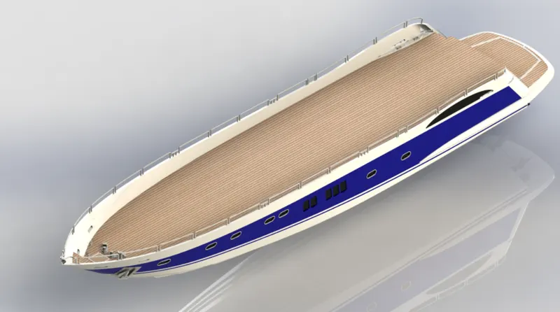
- The body of a boat or ship is called its hull. The gunwales are at the upper edges of the boat's or ship's hull. The gunwales provide extra rigidity for the hull. The cross-section of the stern, where you attach an outboard motor, is called the transom.
- A hull is a watertight body of a ship or boat. The hull may open at the top (such as a dinghy), or it may be fully or partially covered with a deck. The line where the hull meets the water surface is called the waterline.
- The hull of a ship is the most notable structural entity. Define the hull; it can be said that it is the watertight enclosure of the boat, which protects the cargo, machinery, and accommodation spaces of the ships from the weather, flooding, and structural damage.
- The hull is a water-weight vessel body that may be open or partially covered with a deck.
- Hull has several water weight decks and bulkheads as the central transverse membrane.
- The intermediate member of the hull consists of grinders, webs and stringers.
- There may be longitudinal members for strengthening purposes, depending on the structural arrangements.
Commands used to model:
In Sketch
- Line
- Spline
- Circle
- Rectangle
- Arc
- Slot
- 3-D Sketch
- Sketch Picture
In Surface:
- Extended Surface
- Lofted Surface
- Surface fill
- Surface Trim
- Surface Knit
- Delete Face
In Features
- Projection curve
- Reference Plane
- Spilt
- Split Line
- Extruded Boss/Base
- Revolved Boss/Base
- Swept Boss/Base
- Extruded Cut
- Linear Pattern
- Fillet
- Chamfer
- Mirror
Garage Door:
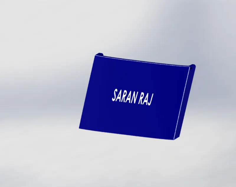
- One of the most popular types of garage doors is Overhead doors. They are named such because they are lifted via a track or rail until they are horizontal to the ceiling. Overhead doors are either operated manually or motorized using a remote unit that brings the door up and lowers it again.
Commands Used to Model
In Sketch
- Line
- Spline
- Circle Text
In Feature
- Extruded Cut
- Reference Plane
- Fillet
- Shell
- Mirror
SuperStructure:
- Aboard ships and large boats
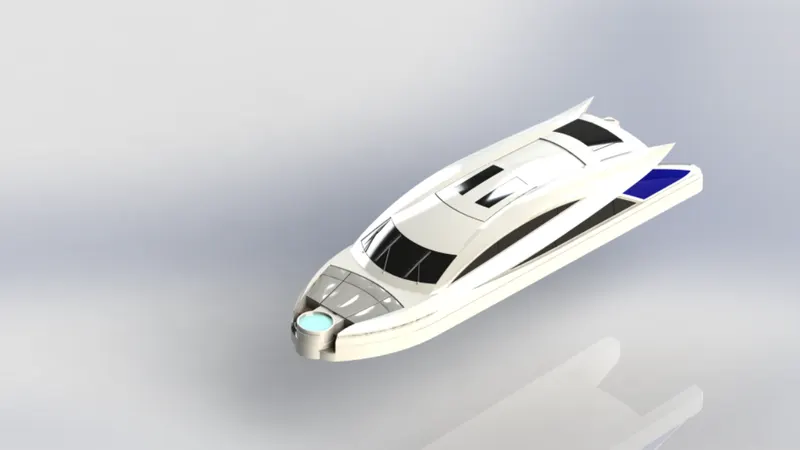
- On watercraft, the superstructure consists of the parts of the ship or a boat, including sailboats, fishing boats, passenger ships, and submarines, that project above her main deck. This does not usually include its masts or any armament turrets.
Commands Used to Model:
In Sketch
- Sketch Picture
- 3D Sketch
- Line
- Spline
- Circle
- Rectangle
- Centerpoint Arc
In Surface
- Extruded Surface
- Swept Surface
- Ruled surface
- Knit Surface
- Trim Surface
- Extended Surface
- Filled Surface
- Lofted Surface
- Fillet
- Chamfer
- Thicken
In Features
- Projection Curve
- Reference Plane
- Convert entities
- Split
- Split Line
- Extrude Cut
- Mirror
Front Seat:
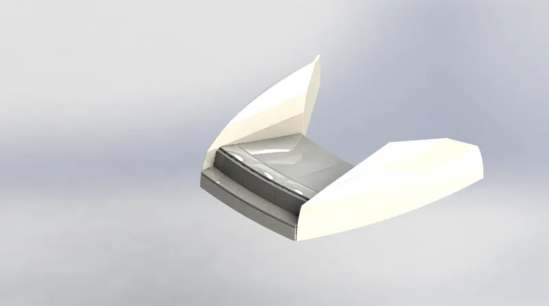
- The front seat features two connected seats built back from one another. They have a built-in storage unit underneath them. Lounge seats can also fully recline right back to make it easier to kick your feet up and get more comfortable.
- The Front seat in our model was placed before the superstructure, and also it has sun pads to rest on it. Sun pads are a great way to reclaim lost space on our boat.
Commands Used to Model:
In Sketch
- Sketch Picture
- Line
- Spline
- Circle
- Arc
In Surface
- Extruded Surface
- Lofted Surface
- Filled Surface
- Trim Surface
- Knit Surface
- Swept Surface
In Feature
- Extruded Cut
- Revolved Boss/Base
- Chamfer
- Fillet
- Mirror
- Dome
Middle Seat:
- The middle seat in our model was placed just behind the structure.
- It is provided With a luxury table to dine out. It also is used to have casual meetings with co-passengers.
Commands Used to Model:
In Sketch
- Sketch Picture
- Line
- Rectangle
In Features
- Extruded Boss/Base
- Chamfer
- Fillet
- Mirror
- Reference Plane
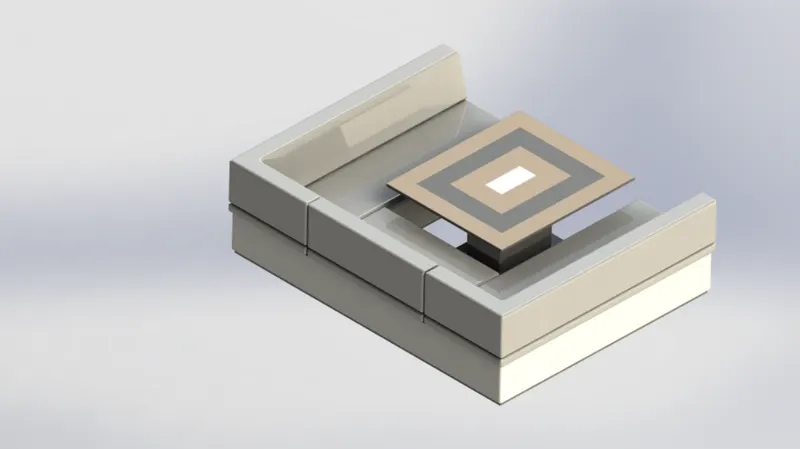
Rear seat:
- The Rear-seat was placed at the end of the deck surface.
- The rear seat consists of racks and steel doors for our stairs.
- The flag was also placed behind the rear seat since it's the end part of our yacht. The back seat was also provided with slots to rest the glass or mug to have a nice view from the boat while having a drink.
Commands Used to Model:
In Sketch
- Sketch picture
- Line
- Spline
- Circle
- Arc
- Rectangle
In Surfaces
- Swept Surface
- Extruded Surface
- Offset surface
- Filled Surface
- Knit Surface
- Ruled Surface
- Lofted Surface
In Features
- Reference plane
- Extruded Boss/Base
- Revolved boss/Base
- Fillet
- Mirror
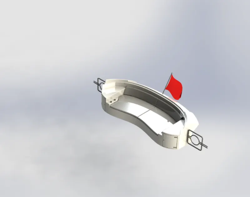
Radar Mast:
- A mast is a vertical ship structure mounted on the bridge and forwards the forecastle towards the ship's bow. It accounts for the support platform for the ships derrick and hold necessary equipment such as radars, navigation light and ships horn in case of the foremast.
- They are made of high tensile steel with added rigidity based on the size of derricks it holds. Besides that, a ship's main mast is also used to hoist the ship's flag.
Commands Used to Model:
In Sketch
- Sketch picture
- Line
- Spline
- Rectangle
- Arc
In Feature
- Extruded Boss/Base
- Lofted boss/Base
- Revolved Boss/Base
- Swept Boss/Base
- Reference Plane
- Projection Curve
- Fillet
- Mirror
- Dome
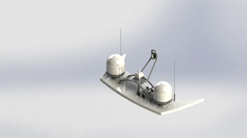
Assembly:
- You can build complex assemblies consisting of many components, parts or other groups, called subassemblies. For most operations, the behavior of members is the same for both types. Adding a feature to an assembly links the body and the component.
- The components and sub-assemblies exist in documents separate from the assembly. For example, a piston can be coupled to other parts in an assembly, such as connecting rod or cylinder. This new assembly can then be used as a sub-assembly in an assembly of an engine. The extension for a Solidworks assembly file name is SLDASM.
Assembly Commands:
Smart Mate:
- A Smart Mate is an assembly relation created automatically.
Mate:
- A mate is a geometric relationship, such as coincident, perpendicular, tangent, and so on, between parts in an assembly.
Mate Group:
- A mate group is a collection of mates that are solved together. The order in which the mates appear within the mating group doesn't matter.
Sub-assembly:
- A Sub-Assembly is an assembly document that is part of a larger assembly. For example, the steering mechanism of a car is a sub-assembly of the vehicle.
Insert Component:
- We can insert multiple instances of the group of components without the property manager.
Assembly Procedure:
Import all the parts manually by using the insert components option.
- Then fix the hull part by applying the coincident mate to the Top, Right, and Front Planes of the assembly and hull.
- Then, each part applies the necessary mates required by the blueprint using coincident mates, angle mates, distance mates, etc.
- The advanced mate was also used wherever required.
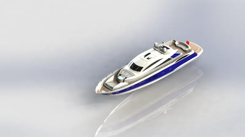
Rendering:
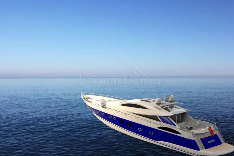
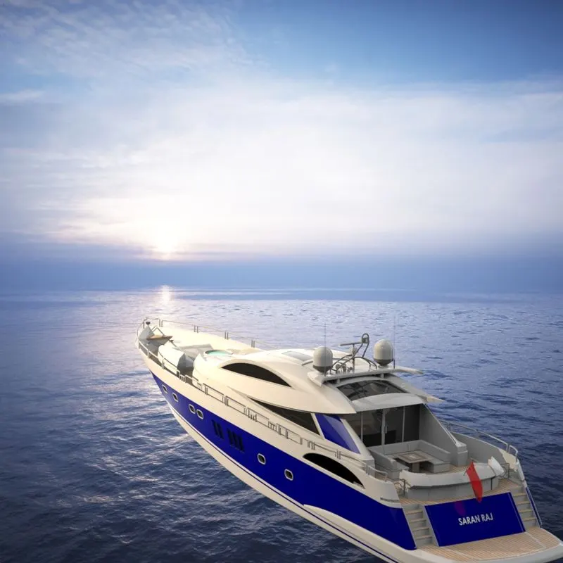
Rendering of the Solidworks model is done using photoview360 and Solidworks visualization.
Photoview360:
- Photoview360 is distinguished from review in that it is not a process of the GPU, and photorealistic renderings can be achieved regardless of the graphics card used. This is because it is entirely calculated on the CPU on your PC and is rendered in a sequential event, and is therefore not dynamic. Photoview360 renderings are more photorealistic than objective views because light rays and reflections are more accurately calculated.
- Photoview360 Renderings Support:
- Self-reflection (reflection of objects in one another)
- HDRI (environmental) Lighting.
Appearance:
- Appearance controls the way the surfaces of the model look. All characters of a model have an appearance applied to them. They can be used at the assembly, part, body, feature or face of a model.
Photorealistic Rendering:
- Photorealistic rendering is the process of photography expect that we are using a computer model instead of a physical model. Before producing a product, we may need to show the customer what the outcome will look like, or we may need to create marketing materials.
The Photoview360 Software:
- Photoview360 is a software solution from solidworks that is fully integrated into the Solidworks software to create a photorealistic image directly from Solidworks models. Rendering may be made from Solidworks parts and assemblies, but not drawings.
Some of the Key features of photoview360 are:
- Photorealistic images directly from Solidworks models.
- Photoview360 interacts with the 3D geometry created with Solidworks software. All changes to Solidworks models are accurately into Solidworks.
- Fully Integrated Into Solidworks.
- Photoview 360 software as a Solidworks add-in.
Solidworks Visualize:
- SOLIDWORKS Visualize allows you to leverage your 3D CAD data to create photo-quality content in the fastest and easiest way–from images to animations, interactive web content, and immersive Virtual Reality. Bring your products to life. SOLIDWORKS Visualize is the “camera” for your CAD data!
Solidworks Visualize Professional:
- SOLIDWORKS Visualize Professional lets you tell a deeper story with your CAD data by generating photo-quality imagery, interactive animations, 360-degree spins, immersive Virtual Reality (VR), etc. Communicate the most intricate design details with ease and beat your competition to the market.
- SolidWorks Professional includes everything that SolidWorks Standard features but adds several features intended to boost productivity for the everyday user who needs to get through their work faster and more efficiently.
Conclusion:
Thus the project Design, Assembly, and Photo-Realistic rendering of a Sunseeker Predator Yacht.