Photo Realistic Rendering
Design, Assembly, and Rendering of American Chopper Bike Using SolidWorks
Objective:
Here the project we have Understand the design process of American Chopper Bike using a design tool in solidworks. To create a Design, Assembly and Rendering of the American chopper by using solidworks and solidworks visualize.
Introduction:
First of all introduce the American chopper motor cycle I designed by using solidworks. This is pretty cool Experience I prefer to learn everyday enthusiastically like what’s next in the design of each and every parts of American chopper. In this project I can learn the design tools and basic concept of solidworks. A chopper is a type of custom motorcycle which emerged in California in late 1950’s. A chopper employs radically modified steering angles and lengthened forks for a stretched-out apeearence. They can be built from an original motorcycle which is modified (“chopped”) or built from scratch. If you’re never ridden a chopper bike, It’s easy to think that they’re uncomfortable as heck! However the truth isn’t as bad. Choppers, in actuality, make for great touring because of their comfort (as well as reliability). Paul Teutul Sr Founder of the American Chopper motorcycle Brand
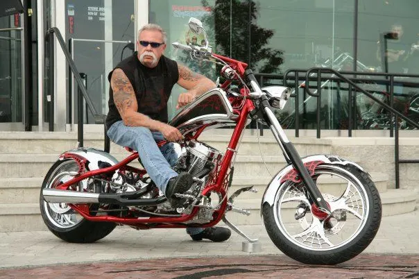
Fig1: Example of an American Motor cycle.
Design tool: SolidWorks
THE SOLIDWORKS CAD software is a mechanical design automation let that lets designers quickly sketch out ideas, experiment with features and dimensions, and produce models and detailed drawings. This document discusses the concept and terminology used throughout the SOLIDWORKS application. It familiarizes you with the commonly used functions of SOLIDWORKS.
PARTS - Demonstrates design methods, tools, and features commonly used to make parts.
ASSEMBLY - Shows how to add parts to an assembly, specify mates, and use in-context design methods.
DRAWINGS – Discusses drawing sheet formats, views, dimensions, annotations, and bill of materials.
Drawing Methodology:
- PARTS
- ASSEMBLY
- PHOTOREALISTIC RENDERING
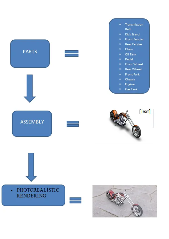
Fig.2 Drawing Methodology.
Explain about the features used in solidworks for American Chopper:
- Boss Extrude:
Example: Picture shows below.
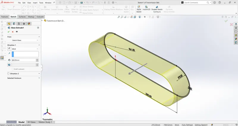
Fig3. Example of Boss Extrude.
Using the SOLIDWORKS Surface Extrude feature, we can extrude the boundary edges of a face of a solid body or edges of a surface body in a customized direction. When we run the Extruded Surface command, two things can happen: Either a sketch is active or preselected or on sketches exists.
- Cut Extrude:
You can also go to the toolbar and click Insert–Cut–Extrude to pull up the Cut-Extrude Feature menu as well. Once the Extrude menu appears on the left-hand side of your screen, it will prompt you to select a plane or sketch that will be used to create the 3D model feature.
Example: Picture shows below.
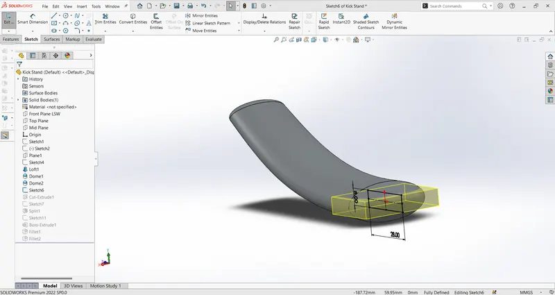
Fig4. Example of Cut Extrude.
- Revolve:
To Create a Revolve features: Create a sketch that contains one or more profiles and a centreline, lie, or edges to use as the axis around which the feature revolves. Click one of the following revolve tools: Revolved Boss/Base (Features toolbar) or Insert>Boss/Base> Revolve.
Example: Picture shows below.
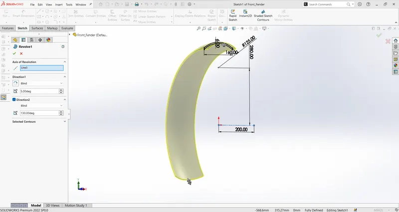
Fig5. Example of Revolve.
- Revolve Cut:
Open a sketch on a face or revolve, and sketch a profile of the cut.
Click Extruded cut or Revolved cut (Features toolbar) or Click Insert> Assembly feature> cut the extrude or Revolve.
Set the option as needed in the Extruded or Revolve Property Manager.
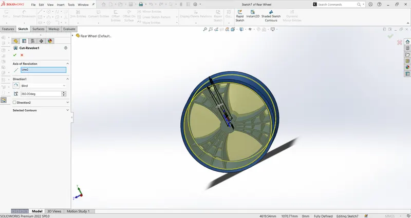
Fig6. Example of Revolve Cut.
- Split:
In a Part, create a sketch to be used to cut the part into bodies. Click Split (Features toolbar) or Insert > Features> Split.
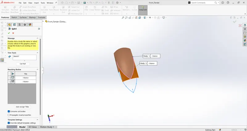
Fig7. Example of Split.
- Dome:
To create a dome: Click Dome on the Features toolbar, or click Insert>Features>Dome. You can create one or more dome features simultaneously on the same model.
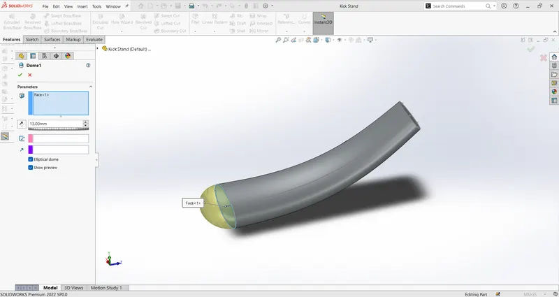
Fig8. Example of Dome.
- Fillet:
Adds fillets or rounds to one or more edges of a part, between two face sets, or between three adjacent face sets.
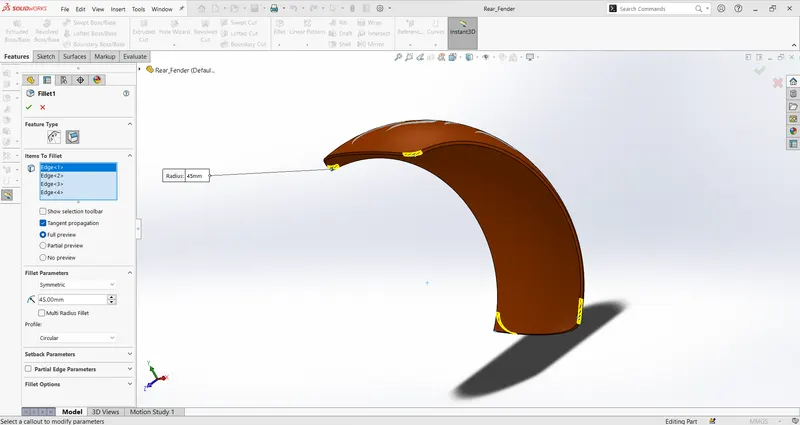
Fig9.Example of Fillet.
- Chamfer:
The chamfer tool creates a bevelled feature on selected edges, faces, or a vertex. To create a chamfer: Click Chamfer (Features toolbar) or Insert>Features>Chamfer. Under Chamfer Parameters, select an item and set parameters.
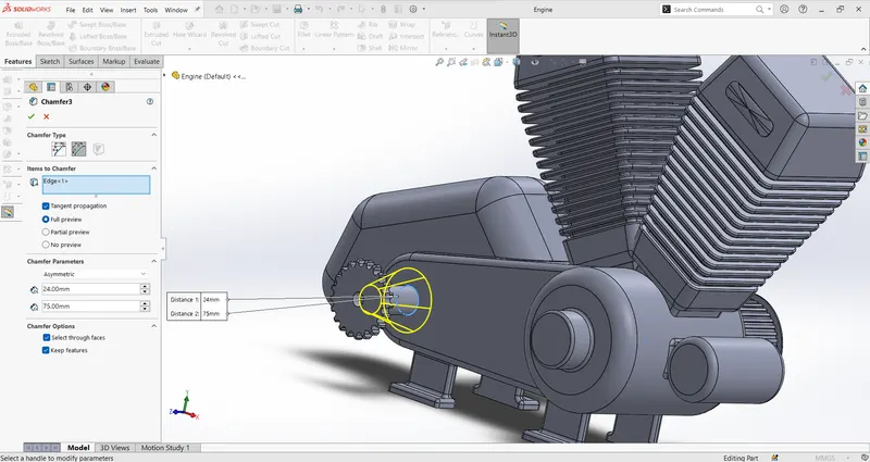
Fig10. Example of Chamfer.
- Linear Pattern:
- Click Insert, Component Pattern, Feature Driven.
- Select the seed components for components to pattern.
- Click in Driving Feature and select the pattern feature in the feature Manager Design tree or a face of a pattern instances in the graphics in the graphics area.
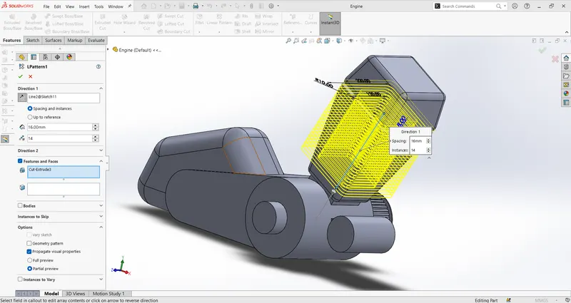
Fig11. Example of Linear Pattern.
- Circular Pattern:
You can create circular patterns symmetrically or asymmetrically in both directions from the seed geometry.
To Create a Circular pattern:
- Create one or more features to replicate.
- Click circular pattern (Features toolbar) or Insert>pattern/mirror>Circular Pattern.
- Set the property manager option.
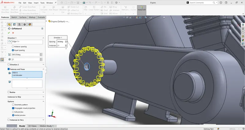
Fig12. Example of Circular Pattern.
- Loft:
Loft Features Blend Multiple Profiles called sections, and transition them into smooth shapes between profiles or part faces. The sections can be curves in 2D sketches or 3D sketches, model edges, or face loops. You can use rails or a centreline and point mapping, to control the shape and prevent twisting.
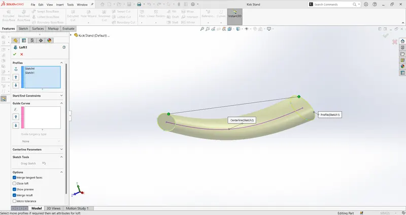
Fig13. Example of Loft base.
- Composite Curve:
On the Curves toolbar or Insert>Curve>Projected. Use this Selection to project a sketched curve onto a model face, select the curve in the graphics area or from flyout Feature Manager design Tree, select the cylindrical face on the model where you want to project the sketch.
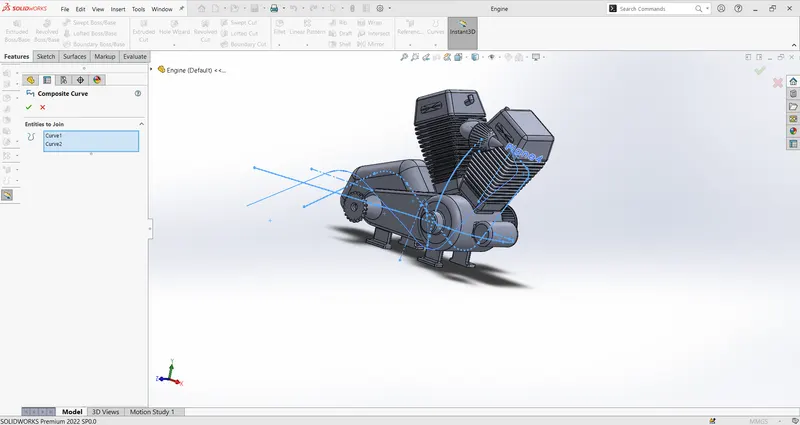
Fig14. Example of Composite Curve.
- Projection curve:
It allows the user to create curves by projecting the selected curves onto the face os the user-defined solid or surface geometry.
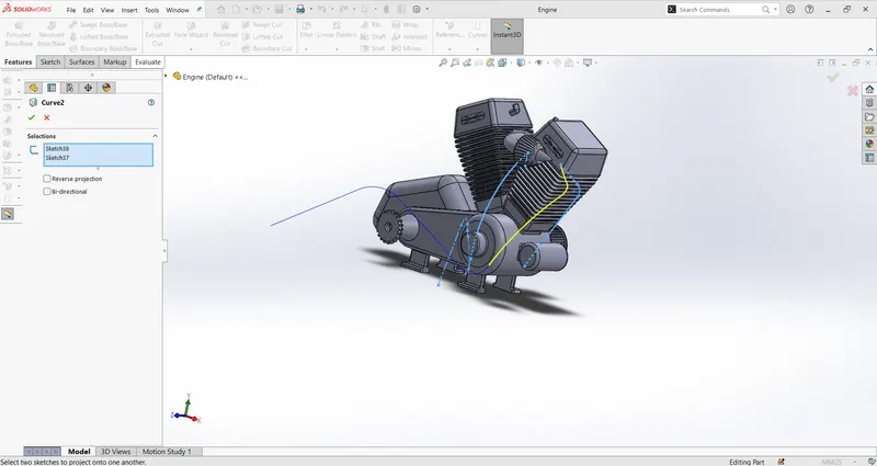
Fig15. Example of Projection Curve.
- Sweep:
Sweep is the one feature in solidworks that helps sweep a closed profile along a closed or open path. In this session, we are going to use a simple 3D object as an exercise to demonstrate the use of the SWEEP command in solidworks.
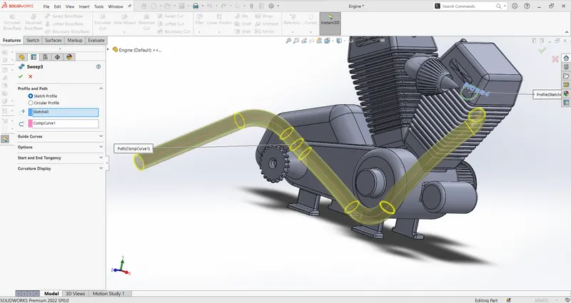
Fig16. Example of Sweep.
- Mirror:
In a part, Select a face or plane to mirror about, and then click Insert> Mirror Part. See Creating Opposite-Hand Versions of Parts. Mirror an Assembly feature. In an assembly, click assembly features (Assembly tab on the Command Manager) and click mirror or click Insert> Assembly feature> Mirror.
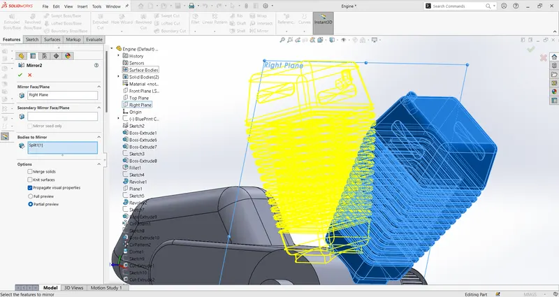
Fig17. Example of Mirror.
- Combine:
In an assembly, you can join two or more parts to create a new part. The join operation removes surfaces that intrude into Each other’s space and merges the part bodies into a single solid volume. To join Parts:Create the parts That You want to join, then create an assembly containing the parts.
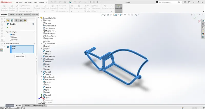
Fig18.Example of Combine.
- Shell:
The shell tool hollows out a part, leaves open the faces you select, and Creates thin-walled features on the remaining faces. If you do not select any face on the model, you can shell a solid pat, creating a closed hollow model. You can also shell a model using multiple thickness.
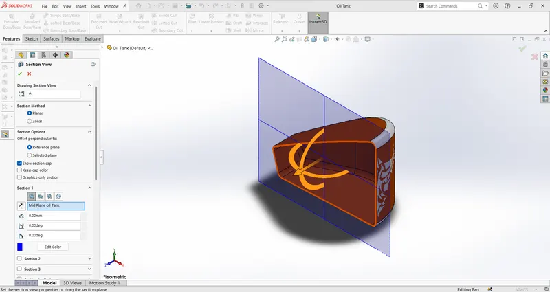
Fig19. Example of Shell.
- Surface Sweep:
Sweep Surfaces are surfaces that are generated from a section curve positioned along a path. Various sweep types are available to extend the sweep definition as follows: Sweep by two guide curves is defined as moving and adjusting a section curve along two guide curves.
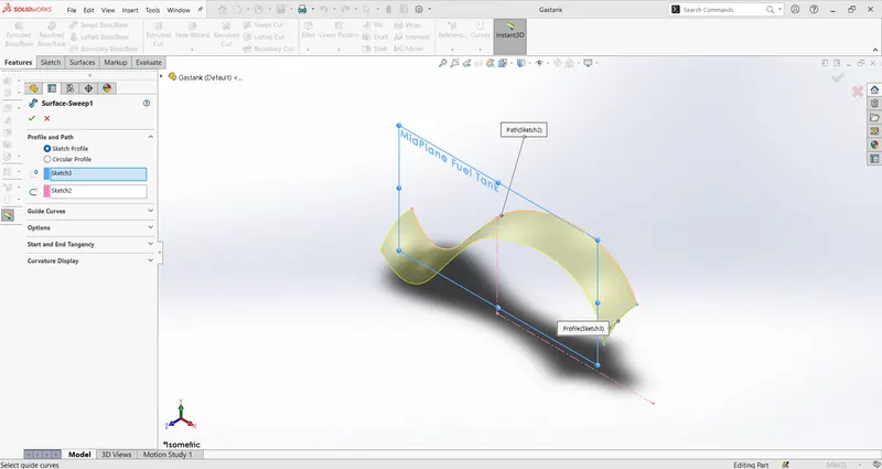
Fig20. Example of Surface Sweep.
- Surface –Trim:
Click cut with surfaces on the features toolbar or click Insert> Cut> With Surfaces. In the Property Manager, under surface cut parameters select the surface or plane to use to cut the solid bodies.
Example of Surface-Trim.
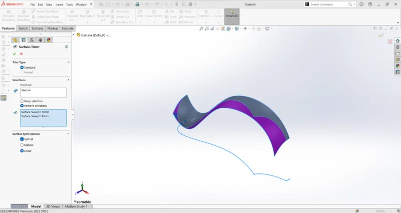
Fig21. Example of Surface-Trim.
- Surface-Loft:
Loft Surfaces are surfaces generated by multiple 3D curves or existing edges creating a smooth tangency between the selected curves. Match points are created between each selection denoting the orientation and path of the loft surface.
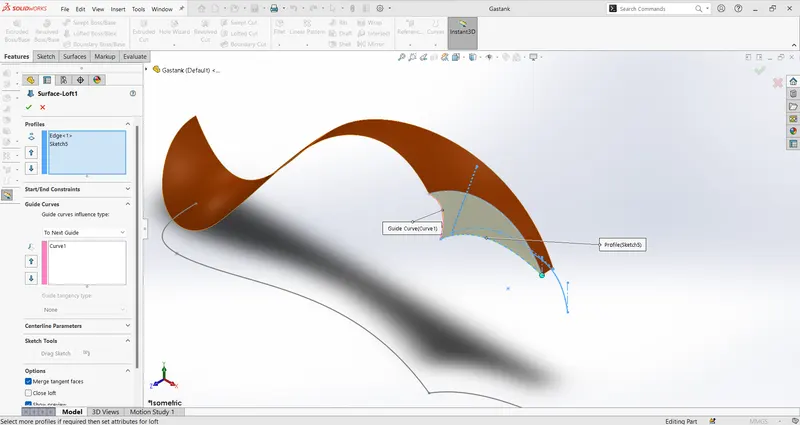
Fig22. Example of Surface-Loft.
- Boundary-Surface:
To create a boundary surface feature, click Boundary Surface (Surface toolbar) or Insert>Surface>Boundary Surface, set the property manager options then click. Curve callouts colours match those used in the property manager. Click callouts to change the Tangent Type.
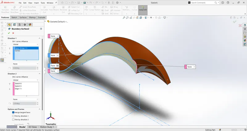
Fig23. Example of Boundary-Surface.
- Surface-Knit:
Use the knit surface tool to combine two or more faces and surfaces into one.
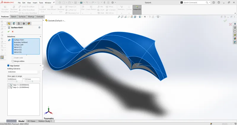
Fig24. Example of Surface-Knit.
- Cut Sweep:
Open a part that has either a closed sketch profile and a sketch path, or a part with a sketch line, edge or curve on the model that you can specify as a path. For a solid profile open a part that has a tool body as the profile as the profile and a sketch path to follow.
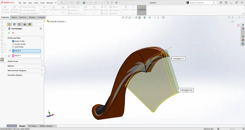
Fig25. Example of Cut Sweep.
- Blue Print:
- Click New.
- In the new solidworks document dialog box select drawing, then click okay.
- Select option for sheet format/size, then click ok.
- In the model view property manager, select a model from open documents or browse to a part or assembly file.
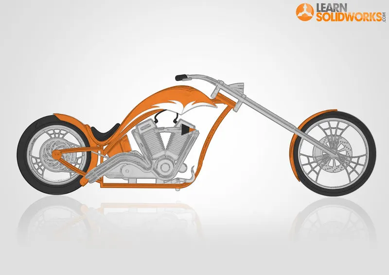
Fig26. Example of Chopper Sketch Picture
PARTS:
- TRANSMISSION BELT
- KICK STAND
- FRONT FENDER
- REAR FENDER
- CHAIN
- OIL TANK
- PEDAL
- FRONT WHEEL
- REAR WHEEL
- FRONT FORK
- CHASSIS
- ENGINE
- GAS TANK
Week-1
- TRANSMISSION BELT:
A belt drive is a transmission system that uses a flexible strip to transfer power. It is used to transmit power one shaft or pulley to another.
Procedure:
- Sketch on the Front Plane Draw a 3 point arc of Radius one side 70mm, another one 61mm respectively.
- Draw a Horizontal Line centre of the both arc 350mm length.
- Create the offset entities 3.5mm of the sketch.
- Exit the sketch go to feature tab select the boss extrude -direction1 blind 88mm to extrude the sketch.
- Fillet the edges of the belt 1mm dimension.
- Apply Appearance of matte rubber on the material.
- Save the part as Transmission Belt.
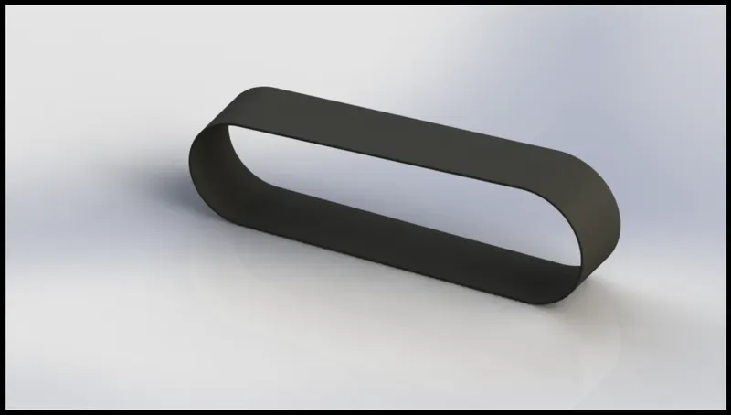 Fig27: Part Model of Transmission Belt.
- Kick Stand:
Most Motorcycles have kickstand that flip out from the side of the bike. A kickstand is a device on a motorcycle that allows the bike to upright without learning against another object or the aid of a person. A kickstand is usually a piece of metal that flips down from the frame and makes contact with the ground.
Procedure:
- Sketch the ellipse on the Front Plane Create the ellipse centre point of the origin and give the dimensions 40mm width and 18mm height.
- Draw the spline perpendicular to the Front Plane Give appropriate weights.
- Create a plane another end of the spline and sketch the ellipse 30mm width and 12mm height, spline and ellipse midpoints make them pierce relation.
- Exit sketch and go to the feature tab select the Loft boos/bass spline of the centre plane and 2ellipse of the references.
- After we make a dome tool for 2ellipse 13mm of one end and another one 5mm.
- Right Plane as a Mid Plane changed the name select it and we create a rectangle from centre of the origin 28mm width and 8mm height exit sketch and go to the feature tab select the extrude cut option.
- Select the top plane centre of the origin with the distance of 4.50mm we create a midpoint line 50mm, split, cut part select the midpoint line it makes the shape below.
- Sketch on top plane centre of the origin create a circle 9mm diameter and extrude up to next.
- Fillet the cut extrude area inside 2mm and again fillet cut extrude edge and extruded circle edge 0.50mm.
- Appearance as given chrome plate and save the part as Kick Stand.
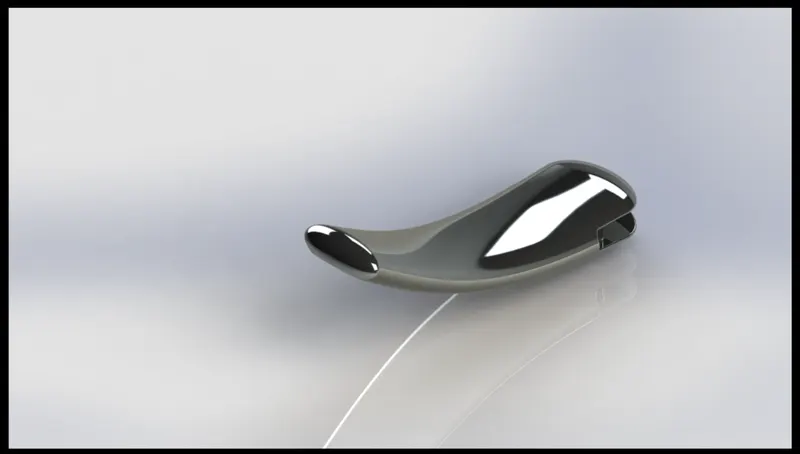
Fig28. Part Model of Kick Stand.
- Front Fender:
Fenders make a tremendous difference when you are riding roads that are wet from drizzle, recent rain, or snowmelt. In a hard rain, you may become wet with clean from above, but fenders will protect your body and motorcycle from the mud and sand kicked up from dirty puddles and rivulets.
Procedure:
- First rename the front plane as vertical plane, Top plane as centre plane, Right Plane as mid plane respectively.
- Start from the vertical plane Draw the 3 point arc 125mm radius and end point distance 160mm apply vertical relation to the centre of arc.
- Make end points of the arcs horizontal, make vertical distance 280mm origin to centre point of the arc.
- Create the offset for the arc 6mm inward, Horizontal construction line along the origin.
- Revolve Direction1 =5deg and D2 =130deg, Sketch the Centre construction line on the fender face and apply dynamic mirror entity for the line.
- Draw a spline centre line of the fender face give appropriate dimensions, use split feature to cut parts consume the body to give aesthetic cut on the top fender.
- Do the split option another side of the fender, Fillets for sharp edges we can apply.
- Appearance we give the painted cat to select sienna and save the file as front Fender.
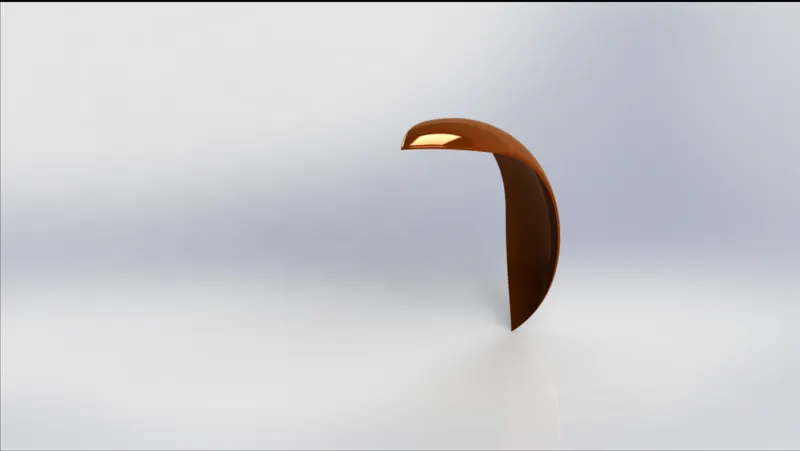
Fig29. Part Model Of Front fender.
- Rear Fender:
It is the same definition of Front Fender But this is for Rear wheel , It is placed and covered on the upper side of the rear wheel.
Procedure:
- Same procedure follows the front fender but the dimensions are differs because of the structure.
- 3point arc 290mm radius and end point distance 364mm, origin to centre point arc 280mm, same 6mm inward offset.
- Revolve D1 =10deg, D2 =140deg, Draw a 3point arc of radius 265mm one side outer face of fender and distance between origin and arc centre point 227mm.
- Split features to cut parts consume body to give aesthetic cut on the top face of the fender, 45mm fillet of all 4 edges of Rear Fender.
- Use shell feature 4mm on inside face of the fender.
- Appearance same front fender we give the sienna and save the file as rear fender.
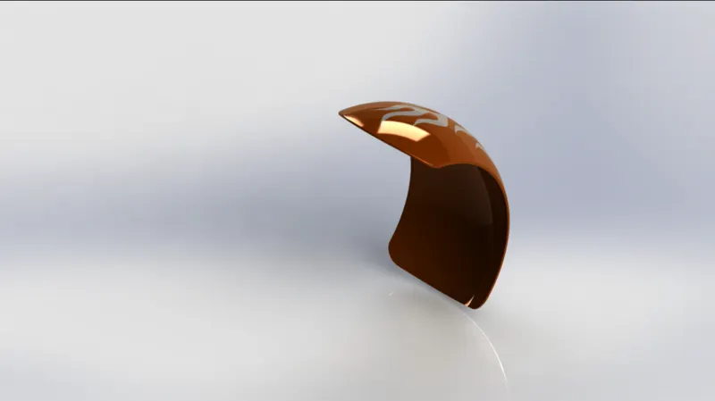
Fig30. Part Model Of Rear Fender.
Week-2
- Chain:
Chain is used as it is both cheap, has very low losses and can transmit a lot of power for it is mass. There are only 2 places where a chain loses power, at each end, and it can accommodate a lot of misalignment and movement of the ends, which the other system cannot do.
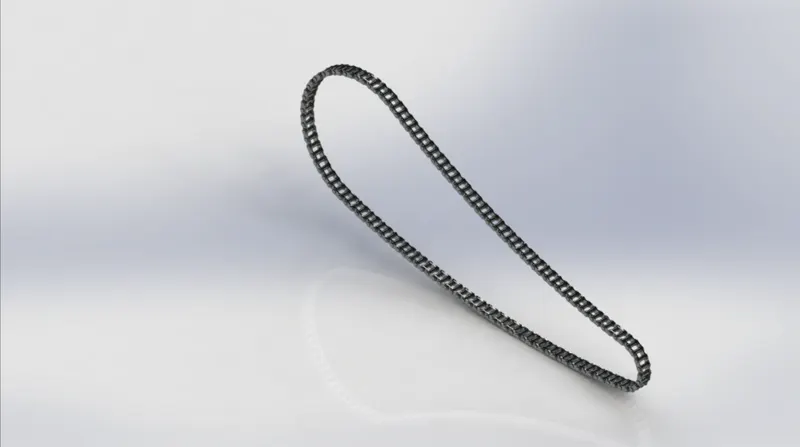 Fig31. Parts Model of Chain.
Procedure for week 2:
- Rename the Planes and 2d sketch with proper Dimensions and add the sketch links on the sketch to extrude the two connecting parts.
- Make a Circular pattern to complete the pattern and mirror the parts to full sketch of chain.
- This while creating Chain is more useful such a tricky parts.
- The above following instructions are Week-2 videos are explained.
- Apply appearance chromium plate and save the file as Chain.
- Oil Tank:
- It is used to Lubrication stored part, oil flows to the engine to reduce the friction of the piston inside the cylinder.
- It placed below the seat on the gear box of the chopper motorcycle.
Procedure:
- Rename the front plane as mid plane sketch the part of top plane.
- Extrude after sketch the mid plane again extrude combine the parts.
- Apply fillet and create shell 3mm as hollow tank.
- Apply appearance as sienna and save the file as oil tank.
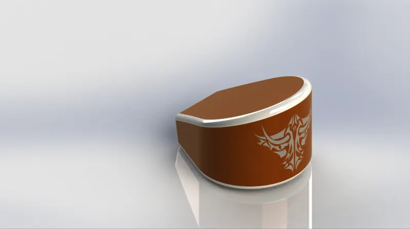 Fig32. Part Model of Oil Tank.
- Pedal:
- It is called as footrest during driving the motorcycle we placed our foot on the pedal, it is mounted on both side of the chassis.
- The brakes and gears are mounted with the pedal of both side, it placed like forward position of fully extended in a comfortable manner.
Procedure:
- Sketch on the front plane using lines, 3point arc, sketch fillet, splines and circle.
- Extrude the sketch 2 circles and sketch on top plane draw a circle to revolve it Dome 3mm and apply fillet.
- Another 2circles to revolve it and give chamfer distance to distance to cone shape of the revolve parts, sketch entities on the circle create to extrude and make circular patterns.
- Apply some fillets, Appearance as chrome plate and sae the file as Pedal.
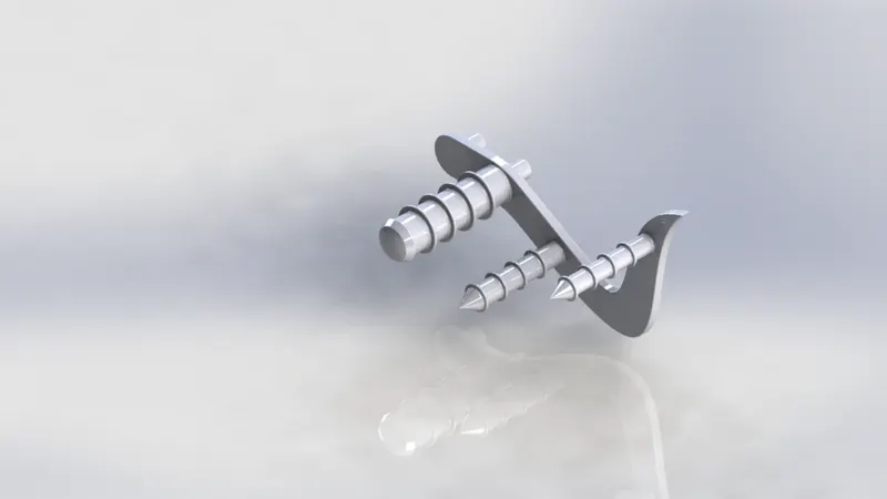 Fig33. Part Model Of Pedal.
Week-3:
- Front Wheel:
- It is most important to move the motorcycles or any other vehicle is wheels.
- This thing placed front end of the fork and it placed in between the front of bike view.
Procedure:
- Tools are used in Rectangle, Line, Arc, Sketch fillet, revolve, extrude, cut extrude, revolve cut, circular pattern, combine, Chamfer, fillet, Appearance.
- It has four solid bodies in the front wheel such as Rim, Rotor, Wheel Caliper, Tire.
- The following constructions are week3 videos explained to design it.
- Add the Appearances For Rim, Rotor, Wheel Caliper, Tire, Rim and Rotor giving a Chromium plate, wheel caliper we gives a sienna and Tyre we gives a Rubber Matte.
- Save the file as Front Wheel.
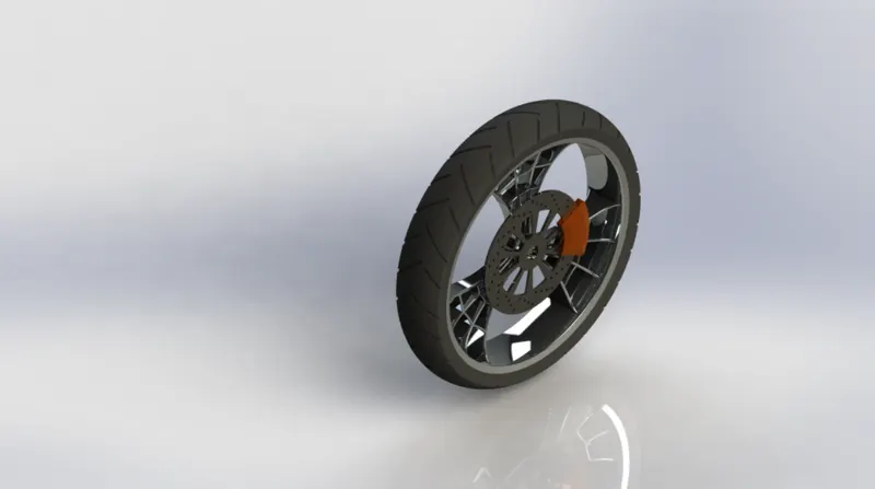
Fig34. Part model Of Front Wheel.
Week4:
- Rear Wheel:
- It is same as front wheel explained before But It placed Behind the Chassis.
- It also having a Solid Bodies Like as Rim, Rotor, Wheel Caliper, Tire.
- This Rear wheel Size of width is big and height little bit shorter comparatively Front wheel.
Procedure:
- Same Procedure follows like Front Wheel But here the construction Dimensions change the Size, Height, and the solid bodies as Rim, Rotor, caliper, Tire.
- But the rear wheel added the Chain Sprocket, it placed with the behind the chassis.
- I design the following constructions in the week4 video.
- Same Appearances gives the rear wheel and save the file as Rear wheel.
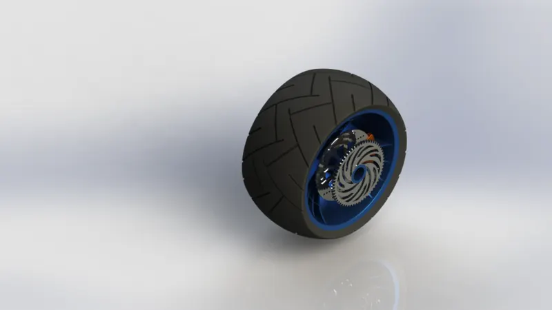
Fig35. Part Model of Rear Wheel.
- Front Fork:
- In this American chopper motorcycle had a lengthy Fork, this fork had Handle bars, clutch and brakes, Head lamps.
- A chopper employs radically modified steering angles and lengthened forks for a stretched-out appearance.
Procedure:
- Here the circle and spline tool using make the projected curves and Sweep the handle of the fork.
- Sketch the one side of the fork and mirror it another side also and combine them.
- Apply fillets and chamfer for edges and head light inside using dome tool.
- And above the construction details followed by the week4 video.
- Save this file as a Front Fork.
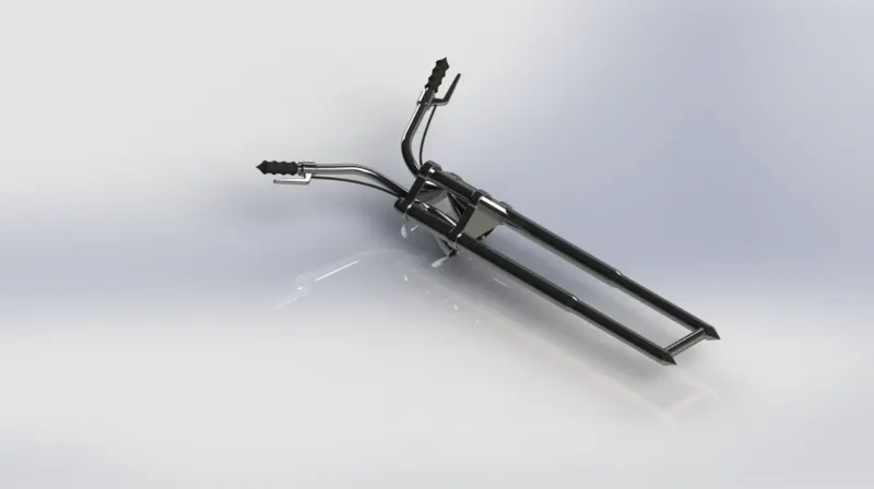 Fig36. Part Model of Front Fork.
Week5:
- Chassis:
- A motorcycle’s chassis or frame forms its skeleton. All the components of a motorcycle, like the suspension, wheels, fuel tank, seats, handlebars etc, are attached to this base structure which lends a motorcycle its strength and ability to handle well.
- Single Cradle Frame is used in American Chopper motor cycle, Carbon Steel is used.
Procedure:
- Important thing to add the Blue print of the chopper motor cycle to design the chassis and guide.
- It is Like a Surface modelling of the design tools like Reference plane, Projection curves to sweep the parts of the sketch and the view.
- The Constructions are made with a help of fully defined sketches and proper dimensions are given.
- I designed the chassis instructions are following by Week5 video.
- Save the file as Chassis.
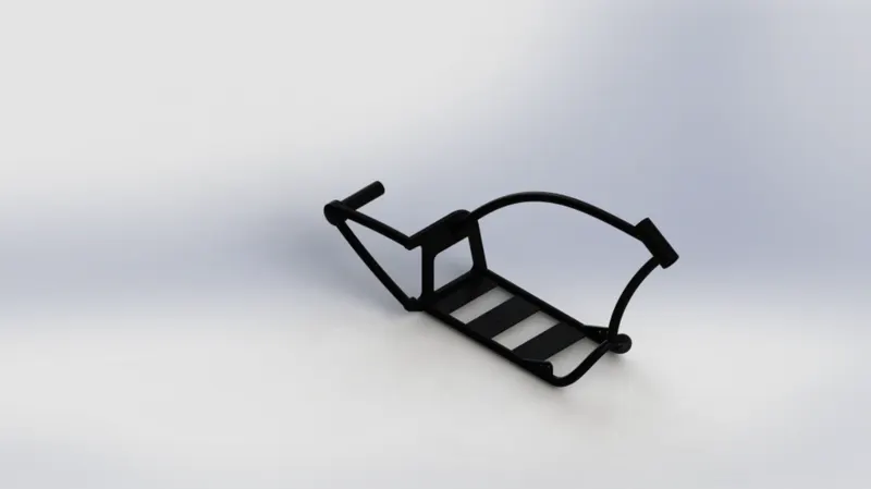
Fig37. Part Model of Chassis.
- Engine:
- You know, we use SNS Motors. As far as the CCs goes, we pretty much go by horsepower and we go from 100 horsepower to 160 horsepower – depending on what the client wants.
- The bike uses one of Dixie Chopper’s 1000cc 32 horsepower (24kw) Generac lawn mower engines which, after modification, provides enough power to be suitable for a motorcycle engine
Procedure:
- The first thing is add the blue print of the chopper place it given dimensions and it is create to guide sketches .
- Sketch the gear box and starter motor with proper sketch they explained in the video.
- Sketch the engine cylinder one side and mirror that another side and create the both side of the fins.
- It’s V type twin engine Give the proper dimension of fillets and chamfer
- Create fuel inlet both side Cylinders, design a sprocket and Air inlet to the engine Cut out on the air filter for aesthetic look and finally design the exhaust system.
- This all are fully defined sketch to design 3d view of engine, apply appearances chromium plate and save the part as Engine.
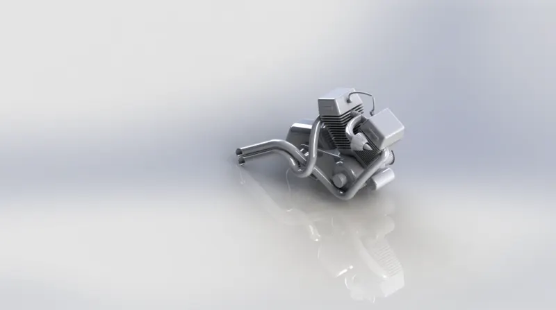
Fig38. Part Model of Engine.
Week6:
The Gas Tank/Fuel Tank:
- It designs a transparent Fuel Tank but driver seat is merged as whole view of Gas tank.
- A fuel tank also called a petrol tank or gas tank is a safe container for flammable fluids. Though any storage tank for fuel may be so called, the term is typically applied to part of an engine system in which the fuel is stored and propelled fuel pump or released pressurized gas into an engine.
Procedure:
- Gas Tank/Fuel Tank was mostly designed as a surface component and features of surface modelling were used extensively.
- Sketch before to get the blue print for reference during the fuel tank/gas tank design process.
- Fuel Tank is designed one side of sketch and other side make it mirror option with the mid plane.
- Sweep Surface create follows the instruction of command with create surface required shape of the fuel tank using trim tool.
- Design the seat closing line with 3 point arc 30mm offset of the edge.
- Extrude cut is made to accommodate the chassis frame, apply some suitable fillets avoids sharp corners.
- Apply appearance Sienna and seat rubber matte, and save the file as Fuel Tank/Gas Tank.
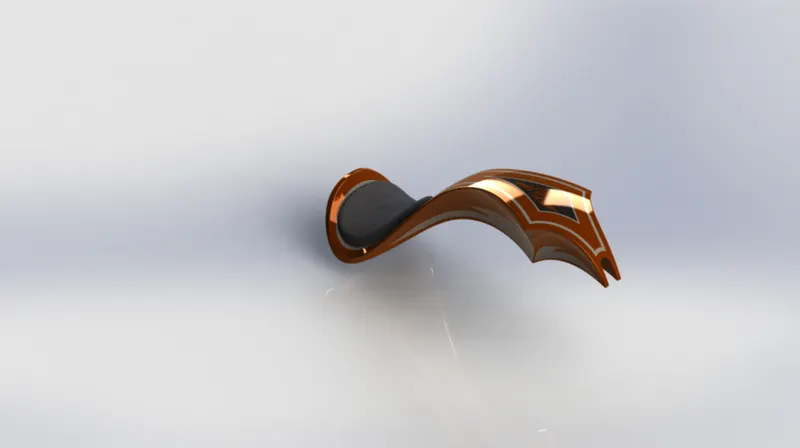 Fig39. Part Model of Gas Tank/Fuel Tank.
Assembly:
Week7:
Chopper Assembly:
- Create new assembly file the first component is import the chassis mate with the front plane of chassis and front plane to get the position.
- Second one import the Engine Component mate in between bottom of the chassis.
- Next one Import to insert the pedal Front end bottom to concentric mattes and matte the surface after mirror the pedal using mid plane of the chassis.
- Next component is kick stand the mates are applied to it, give some angle to move the part like side stand position and take off position 30deg angle.
- Import to assemble the Transmission Belt to two rotating power transmission parts.
- Next one Oil Tank to merge up on the Gearbox of the engine.
- Next Fork matte with the chassis head set the angle for it for Both side rotation like while drive turn the path so give proper angle for it.
- Front Wheel Assemble with the fork where it comes are instruction the following video.
- Rear Wheel Assemble the matte with behind the chassis.
- Front fender placed on the front wheel and Rear fender also placed on the Rear Wheel.
- Gas tank Assemble with the chassis and front fork of the motorcycle.
- Add or Apply Decal on the chopper.
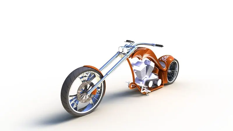
Fig40. Part Model of Assembly Chopper.
Photo Realistic Rendering:
Here, what we are doing Rendering the American chopper using SolidWorks Visualize, now we can rendering using this software change the background little few more appearances adding and start rendering. It’s looks like Photo Realistic View.
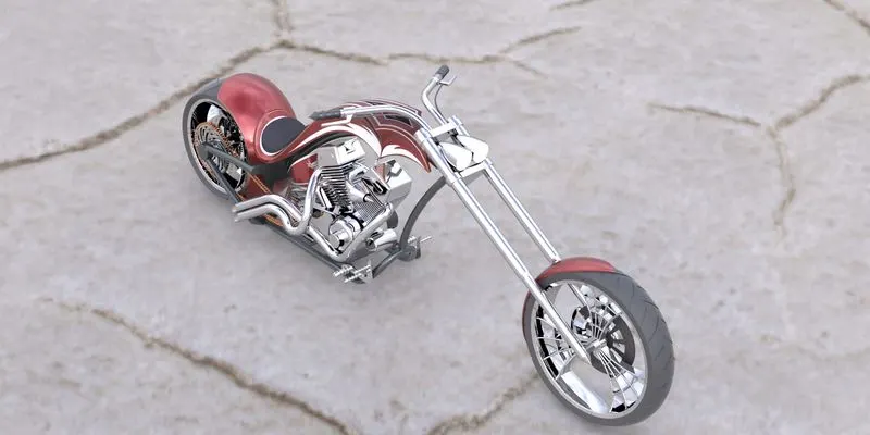
Fig41. Isometric View Rendered Chopper.
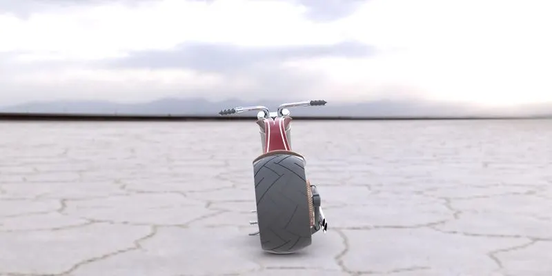
Fig42. Left Side View Rendered Chopper.
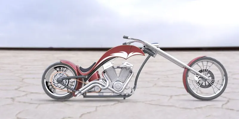
Fig43. Front View of Rendered Chopper.
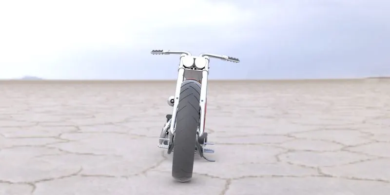
Fig44. Right Side View of Rendered Chopper.
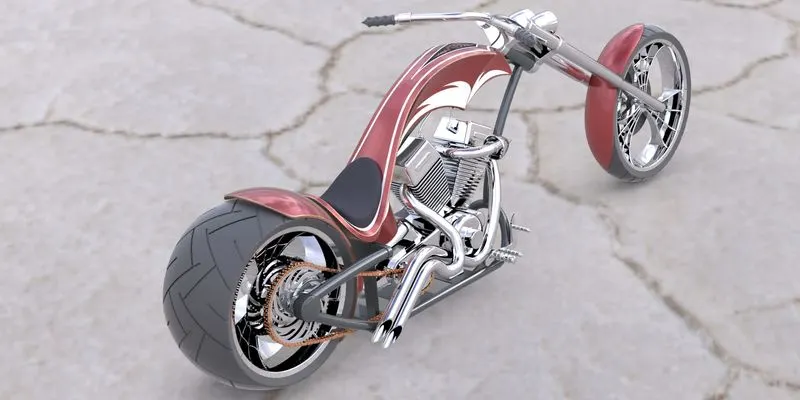
Fig.45. Isometric View2 Redering
Conclusion:
Design, Assembly using SOLIDWORKS and Rendering using SOLIDWORKS VISUALIZE are Successfully Done My Project.