Week 8 - Challenge 6 - Core & Cavity Design
CORE AND CAVITY OF A SWITCH BEZEL
AIM:
- The aim is to design the core and cavity of a switch bezel from the solid component of a switch bezel
- Earlier switch bezel can be design by using a CLASS A SURFACE and creating B SURFACE and C SURFACE to create a surface and solid component from it.
DESIGN PROCEDURE:
- To setup the class-A surface and to creating a tooling axis
- add draft angle
- To create a base surface of model
- To create a B-surface
- To create a C-surface
- To use close surface for creating a solid part model
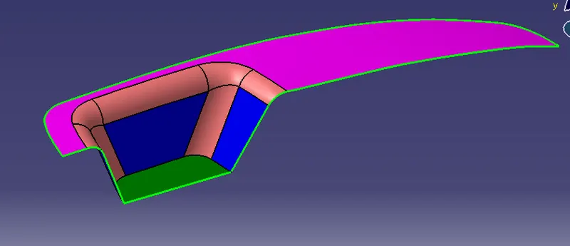
CLASS-A SURFACE:
TOOLING AXIS:
- Tooling axis can be classified into two methods
- direct method
- bisecting method:
- In this model we use bisect method based on the requirement. This method is used for complex components.
- To use AXIS for creating line on zx-plane and zy- plane respective to origins
- To bisect the two lines and create a tooling axis.
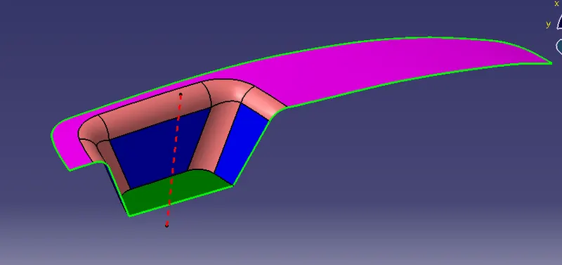
DRAFT ANALYSIS:
- The Drafting analysis was performed on the class-A surface by using the Feature Draft Analysis command.
- Using this command, the compass was set on the main tooling axis and the Draft angle was changed to 3 degrees.
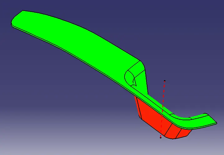
CORE AND CAVITY DESIGN:
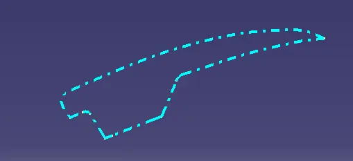
PARTING LINE:
- It intersects the component and parting surface
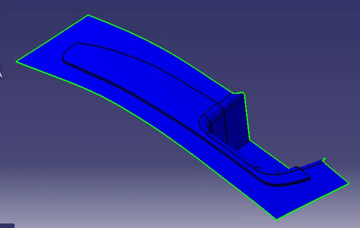
PARTING SURFACE:
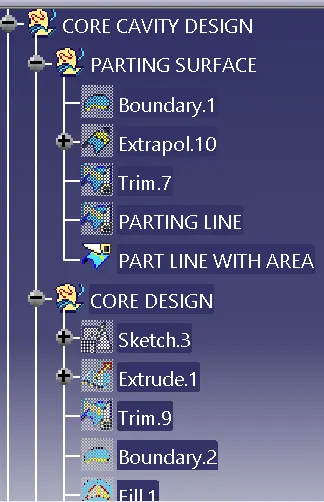
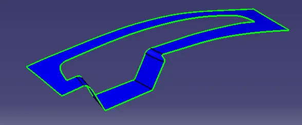
- Parting surface, created for core by trim with the extrapolate C SURFACE with CLASS A and B SURFACE
BASE SURFACE CREATE FOR CORE
- To design a parting surface by select the C SURFACE and make split with the parting line for surface with switch bezel
CORE DESIGN:
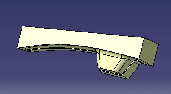
- The create base surface can used for core base
- To draw a sketch and extrude up to required length with the reference of TOOLING AXIS
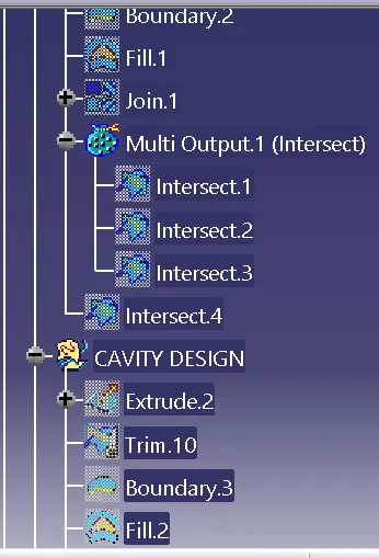
- By using boundry and fill to close and create the core surface
CAVITY DESIGN:
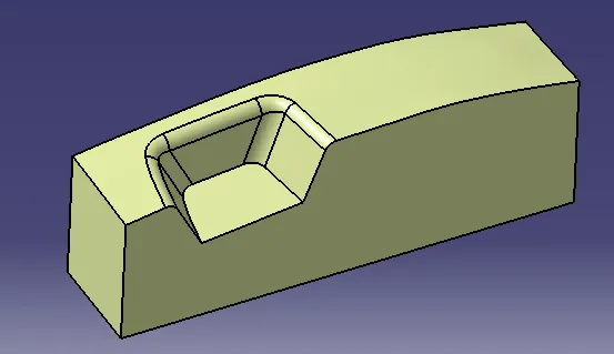
- By taking CLASS C SURFACE and to extrude sketch along opposite to the component and fill the open area by using boundary and fill tool and to create a cavity surface.
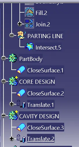
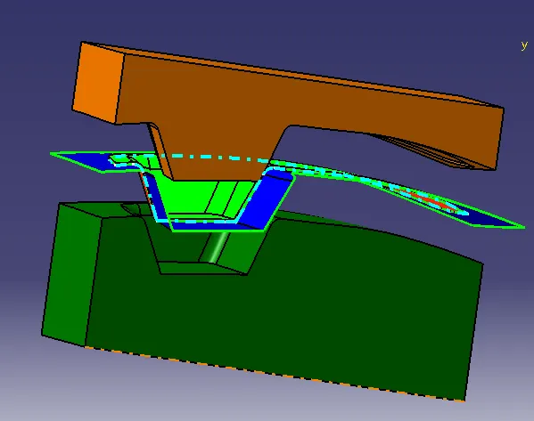
THE SOLID CORE AND CAVITY WITH SWITCH BEZEL COMONENT ALONG PARTING LINE AND SURFACE:
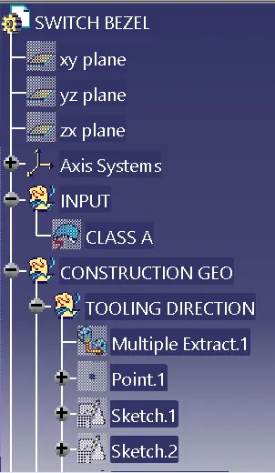
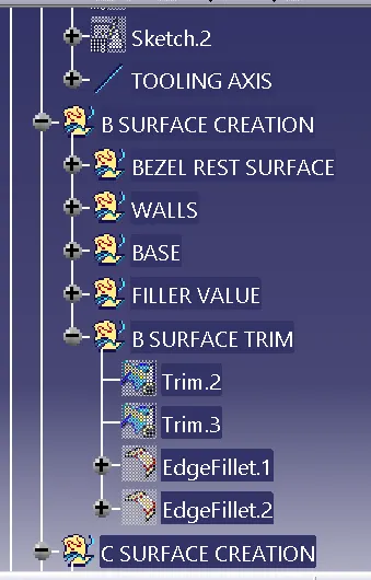
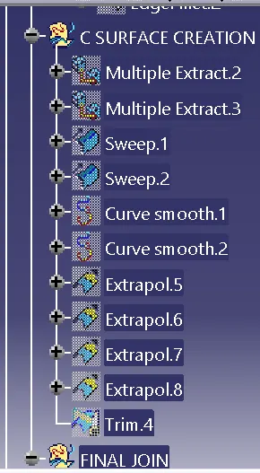
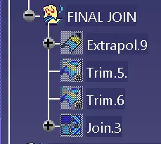
TREE SHOTS: