Week 8 - Challenge 6 - Core & Cavity Design
CORE & CAVITY DESIGN :-
Aim-
Create the Core and cavity blocks for the switch bezel designed
Draft Analysis-
Draft analysis is the most importent thing for a part design process. It says, how Core & Cavity part are going to be and what will be the position of parting line & parting surface. Our tendency is to make the tooling axis along or near about Z axis.
TOOLING AXIS-
The Tooling Direction is basically the direction that the mold pulls a part. The mold is built in two separate pieces, basically. You have a Cavity side and you have the Core side. The Core pulls apart from the Cavity and that's the Dye line or the Tooling Direction.
Process-
- Check for gaps between surfaces for that click on join and then preview.
- If theres any gap between the surfaces join them with a maximum tolerance of 0.003 mm.
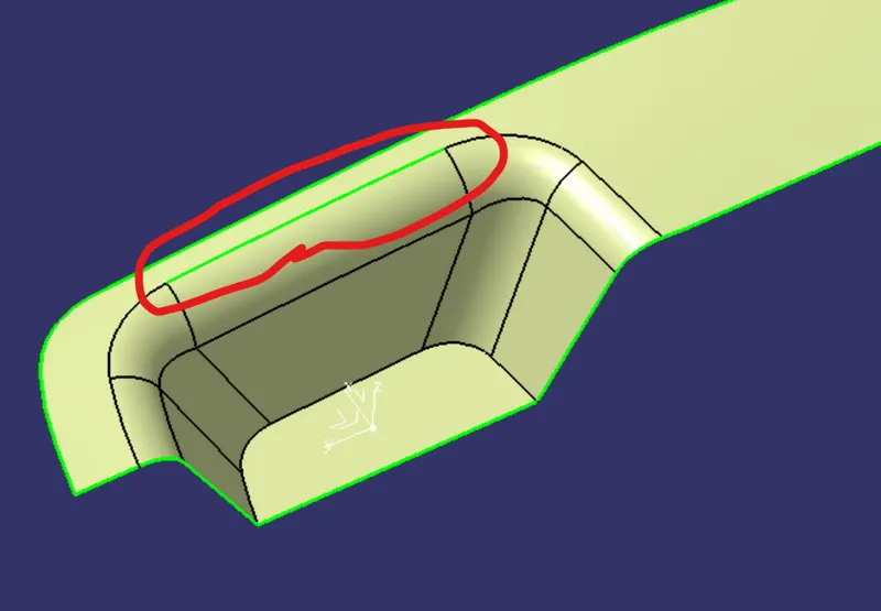
Here we have a gap that we will join using 'Join' command whwre maximum tolerance will be 0.003 mm. So the reasult will be-
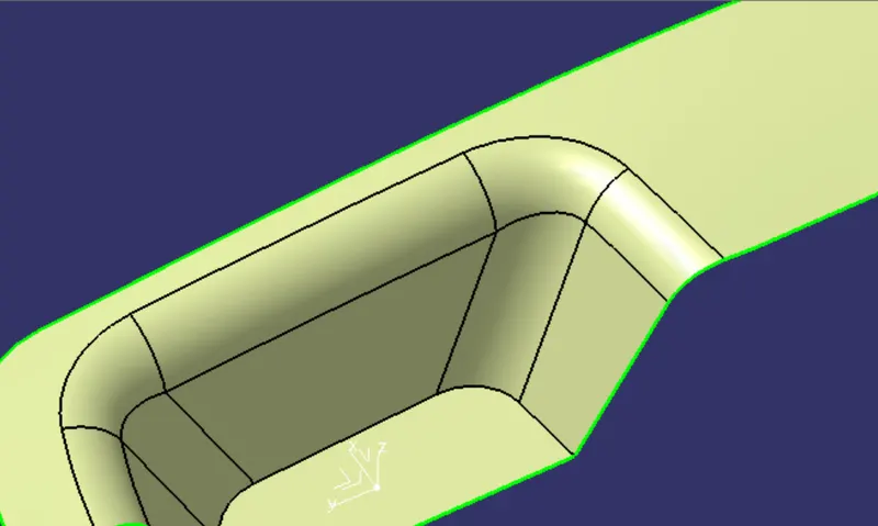
As this part has a dent so we will try to make the tooling axis along that dent. Now we will create cross section along those two perpendicular surface.
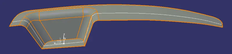
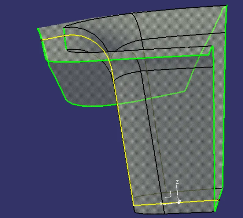
So for first plane two stif surface are there. Create two line along those surface and create a bisecting line with those two lines.
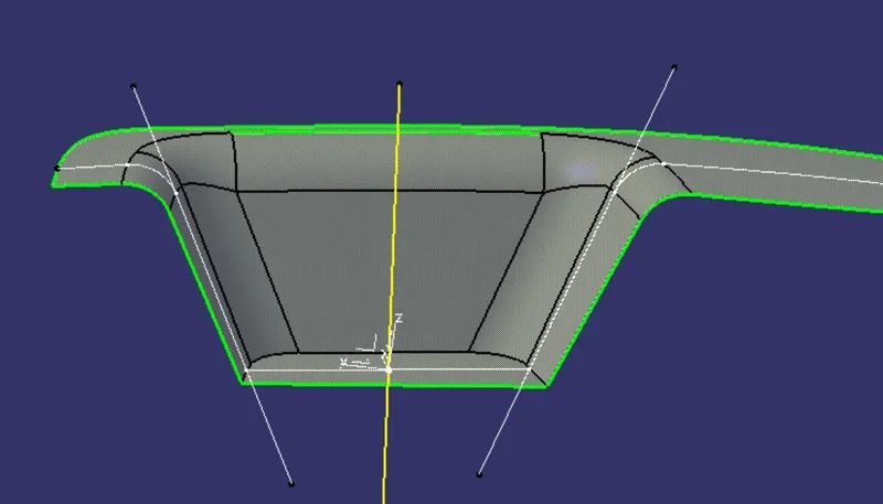
Next create a line along the stif surface of second plane. And make a line with more than 3 deg. angle with that stiff surface line.
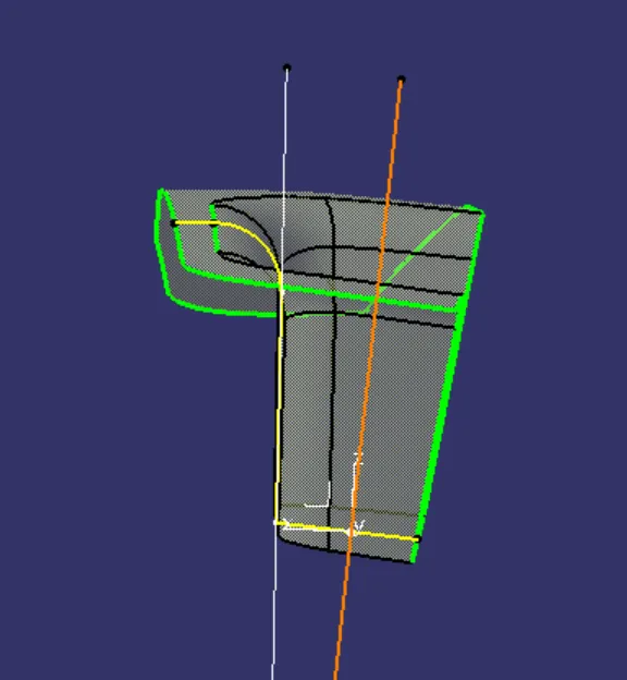
Now make another bisecting line with two bisected line of those two plane. And that will be the final tooling axis.
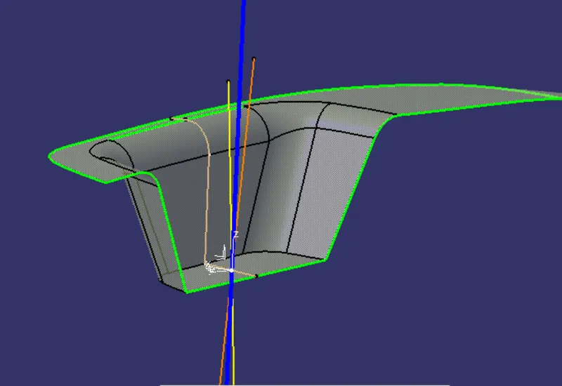
Draft Analysis of Class A Surface-
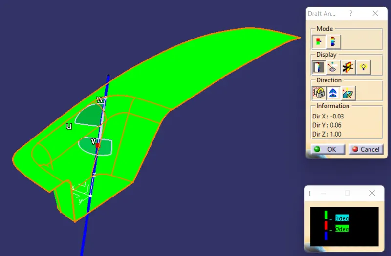
So the above image says that Class A surface cleare the tooling direction.
Draft Analysis of Solid Body-
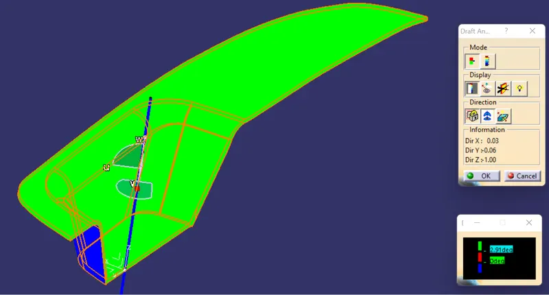
So from the picture we can see that solid body is clearing the draft angle. Both Class A & Class C are clearing the draft angle. For that reason Both Class A & Class C surface are impresented on Core Part.
CORE & CAVITY-
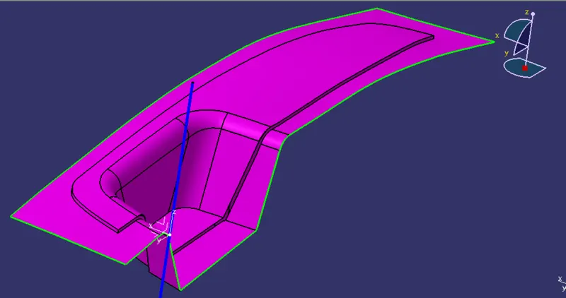
Parting Surface-
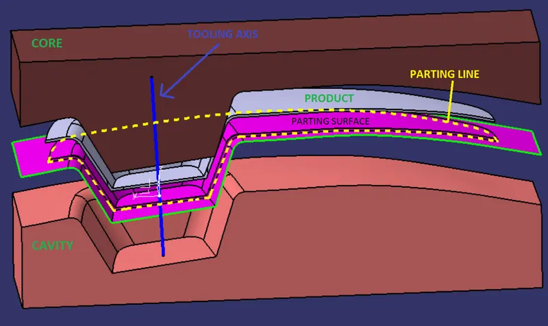
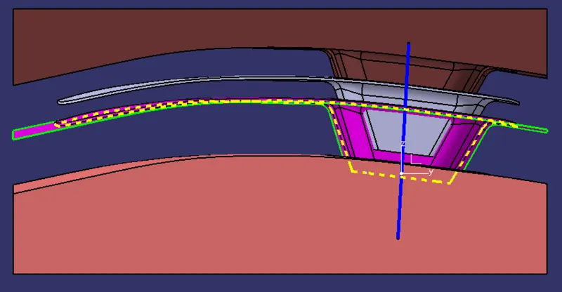
Generally injection mold has two major components : the movable half and the fixed half, during the injecction molding process, these two halves are pressed tightly from a sealed hollow to avoid the melt flow leakage and maintain certain holding pressure, the pressed surface are called parting surface , usually parting surface are the biggest projection outline of the part.
To create the core for thi spart extend Class A surface have to be trimmed with Class C surface keeping the main working surfaces. Then trim the perticular surface with Class B surface trimming working surface area of Class B. The reasulted surface will be the parting surface.
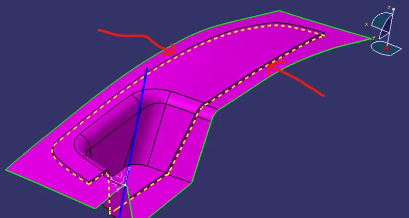
Parting Line-
A parting line is an inevitable part of injection molded products. It is the line of separation between where two halves of a mold meet. It manifests itself on injection molded parts as a line that runs the entire perimeter of the part. In most parts, it is just a line that runs straight down the middle
Core-
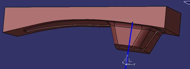
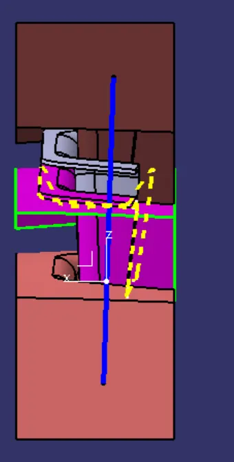
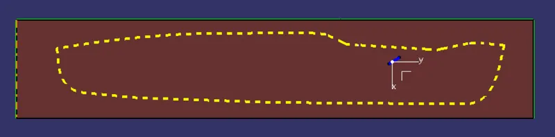
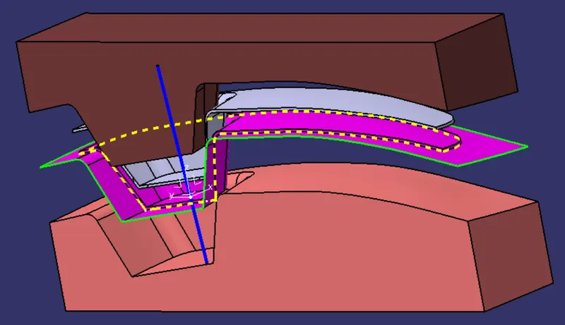
A portion of the mold that goes inside a cavity to form the interior of a hollow part. To create the core part make a rectangle on the plane of Parting surface. Make sure that rectangle cover some extra area beyond the product surface. Extrude the rectangle along the perpendicular axis of parting surface. Then trim the extruded surface with parting surface profile and make that solid.
Cavity-
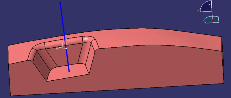
Cavity part havr to with Class B surface. Previously make rectangle have to extrude along Class B surface with same way and trim that with Class B surface. After closing the opposit side with 'fill' command, part have to make solid.
Translated View-
3D Views-
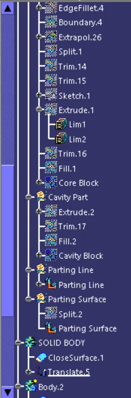
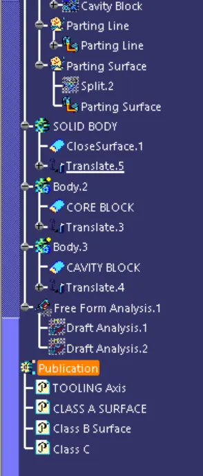
Tree Structure of geometrical sets -
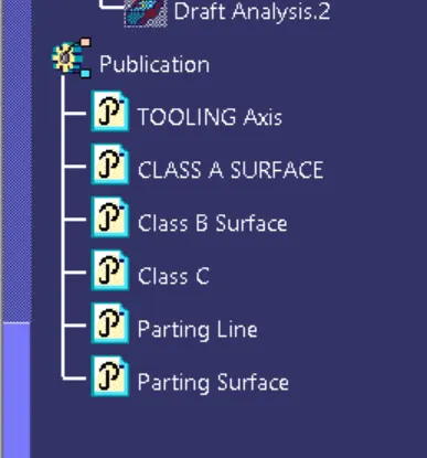
Publications-