Week 8 - Challenge 6 - Core & Cavity Design
Report
Tooling Axis
In order to make the tooling axis we must identify the a hole/pocket, in this case we have a pocket,
So we take the center of the base of the pocket as the surface for the tooling axis and make a line perpendicular to it.
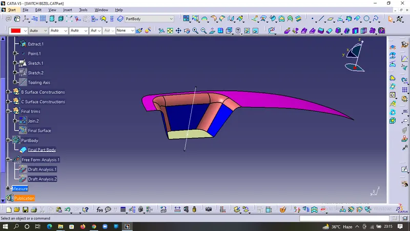
As we have identified that only 1 wall is almost parallel to our dummy toolind axis so now we make as line that is at a angle to atleat 6 degree to 8 degree from the wall (as we have to make a bisecting line the angle will reduce after making the bisecting line ).
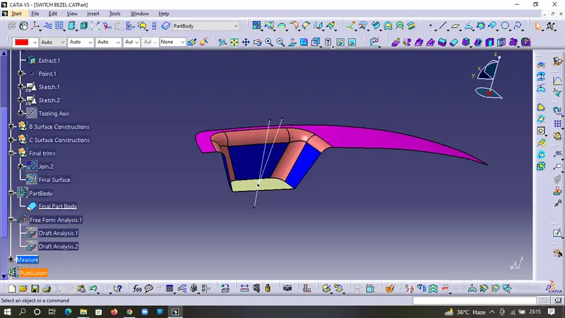
Now make a bisecting line betwee the dummy tooling axis and the 8 degree line, the final outcome is our Tooling Axis.
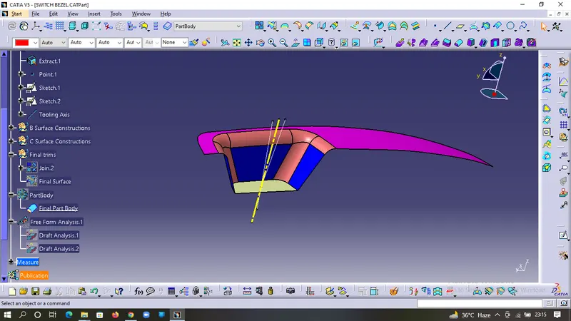
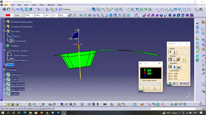
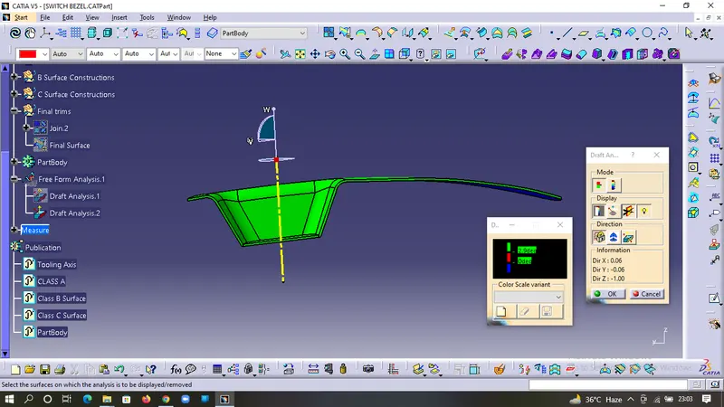
Now to validate the tooling axis we do the Draft Analysis
For Draft analysis we need to change to material mode and then start the draft analysis.
First move the axis flag on the top of the tooling axis and lock it.
Then pick the part body and select & customise the color scale, if any surface shows abnormalality then correct the tooling axis otherwise finalize the tooling axis.
Core & Cavity
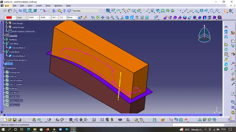
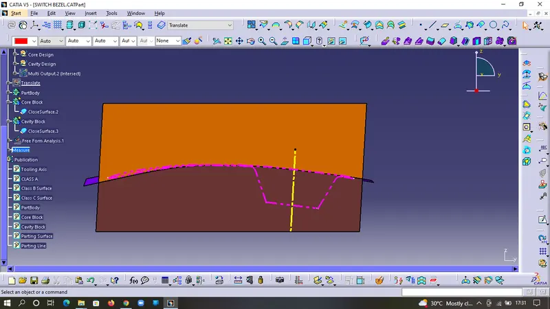
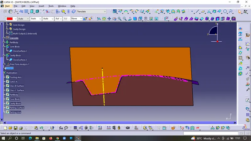
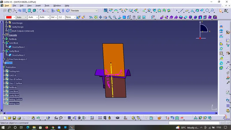
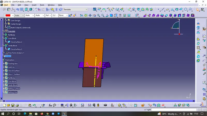
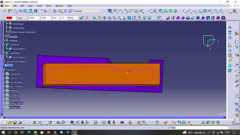
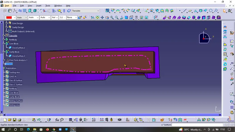
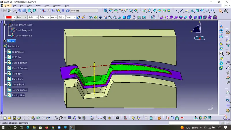
The Core & Cavity are the blocks between which our component is made, so to make the core we will use the Class A surface and then extend it with the Class C Surface till Class B.
Then to make the Cavity we use Class B Surface,
In order to avoid any deformation due to flash & other defects we try to make the parting line & surface at junction of class C & B
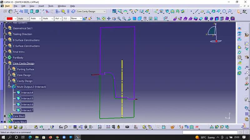
Description of Figure
- Blue - Core
- Green - Cavity
- Brown - Parting Surface
- Yellow - Tooling Axis
Screenshots of the Draft analysis report for both the switch bezel plastic component
Class A Surface
Final Plastic Component
Screenshots of the core and cavity blocks in various orientations (Isometric, Front, Side, and Top View)