Week 8 - Challenge 6 - Core & Cavity Design
Objective: The main objective of this challenge is to design a Core and Cavity for a Switch Bezel' in CATIA V5 with the help of a surface workbench.
What is Draft Analysis?
Draft Analysis
For molded or cast parts, the draft angle is the amount of taper perpendicular to the parting line. It is measurable in degrees. Because plastic shrinks and sticks on molding surfaces as it cools, we draft the walls of the plastic part so that it ejects or breaks free from the molding surfaces more easily and without dragging. To reduce the risk of damage to the parts and ensure ejection, a functional injection molding part must have drafts on both the cavity and core sides.
Nominal values for Draft angles
- 3 Degrees is a nominal draft angle
- 5 Degrees can also be manufactured. Increasing the manufacturing cost
- 7 Degrees is considered for Textured surface parts
Importance of Draft in injection molding
- Reduces the possibility of part damage due to friction during the release
- Reduces mold wear and tear
- Ensures a uniform, smooth, unscratched finish
- Ensures the integrity and uniformity of other surface finishes and textures
- Reduces overall cooling time by reducing or eliminating the need for unusual ejection setups
Creation of Tooling Direction -
1. considering the ejection from the cavity of the mold after manufacturing the switch bezel. (must have the nominal 3- degree draft angle)
2. Hence the tooling direction is created by considering the above factor and bisecting method is used.
3. The base surface of the class - A was extracted and a point at the centre is created and an axis system was inserted to the point with the current feature is disabled.
4. Then, by selecting the quick analysis mode, the nominal value will be 3 degrees and checked for the component's draft angle
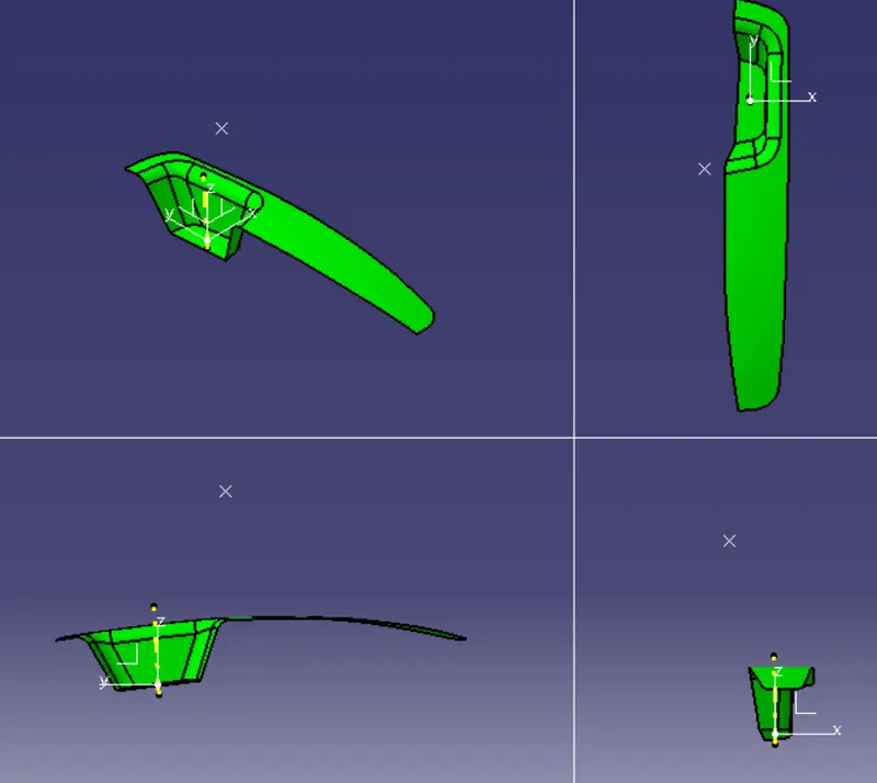
5. The green colour area shows that it satisfies the 3 degree draft angle. If not satisfied then by using the Runnind point the area is measured and then altered to get a succesful draft for the created tooling direction.
6. Min. 0.3 degree of deviation is allowable so we take 2.9 value for draft analysis.
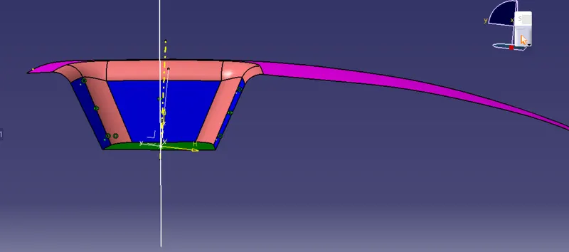
Draft Analysis Images in Different Direction -
Creation of core and cavity -
Parting Surface
A parting surface is a surface that separates the mold block into two parts – the core and the cavity.
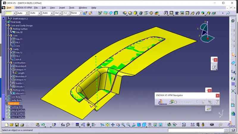
Parting Line
The parting line of a die-cast component represents where the two different sides of the mold come together. This line often (but not always) marks the border between the inside and outside of the part.
The Purple Line represents the Parting Line for this Model
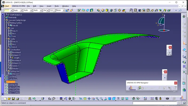
Core & Cavity
The Mould Core & Cavity are the shaped sections in either half of the mould tool which give the plastic product its final shape. The hot molten material is injected into the core & cavity and then sets hard into shape. The design of the core & cavity is essential in the correct formation of the product.
Core
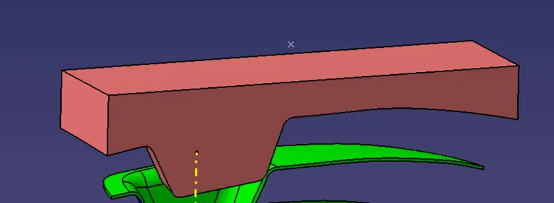
Cavity
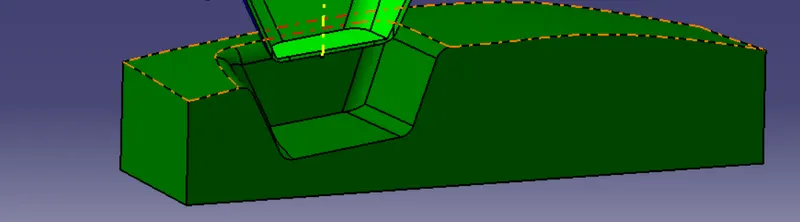
Core and Cavity images -
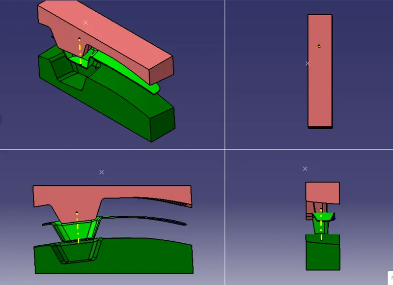
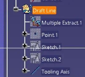
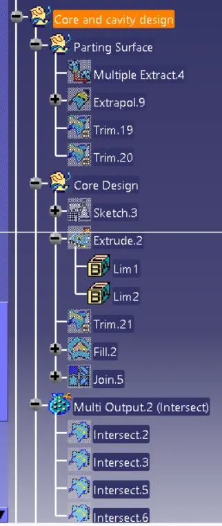
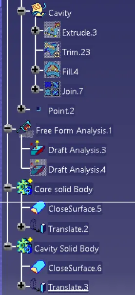
Tree structure of commands used to create core and cavity -