Week - 4
1. Implement control logic of a “washing machine” using Stateflow
- Aim :-
- Impliment control logic of washing machine using stateflow by giving certain condition asper power input and water asper this input, machine operates and obtain output by lamp light.
- Objective :-
- To impliment control logic of washing machine using stateflow asper given-
- if the power supply is available the system gets activated.
- if the power supply is not available, stop the process and indicate through LED.
- Soaking time should be 200 sec.
- The rinising happen for 20 seconds and dryrun for next 50 seconds.
- After all the process have completed turn on the finishe LED.
- Working of washing M/C -
- All the important part of the clothes washer are electricaly controlled, including inner drum, the valves, the pump and the heating the programmer is like is like the conductor of an orchestra, switching these things on and off in a sensible sequence that goes somthing like this.
- You put your clothes in the machine and detergent either in the machine itself or in a tray up
- You set the program you want and switch on the
- The programer opens the water valves so hot and cold water enter the machine and fill up the outer and inner drums. The water usualy enters at the top and trikle down through the detergent tray washing any soap there into the.
- The programer switches of the water.
- The thermostate measure the temp. of incoming if its too cold, the programer switches of the heating elements, this work like and kettle or water boiler.
- When the water is hot enough, the programmer makes the inner drum rotate back and forth, soshing the clothes through the soapy
- the detergent pulls the dirt from your clothes and trap it in the
- the progarammer opens the valve so the water drains from both then it switches on the pump to help empty the water away.
- the programmer opens the water valve again so clean water enters.
- The programmer make the inner drum rotate back and forth so the clean water rinses the it empties both both drum and repeats this process several times to get rid 0f all the soap.
- when the clothes are rinsed, the programmer makes inner drum rotate at really high speed and around 80 mph ( 130 km/h). The clothes ate fliung against the outside edge of the inner drum, but the water they contain is small enough to pass through the drums tiny holes into the outer spinning gets your clothes dry using the same idea as a centrifuge.
- The pump removes any remaining water from the outer drum and the wash cycle comes to on
- You take your clothes out of marvel at how clean they
- But there is still broblem to drying your clothes to figure.
- Steps :-
- create a chart clock for defining the stateflow as per given condition
- inside it a circular junction is to terminate the signal flow and return null value.
- if power is off i.e. 0, the process is terminated at the junction else 1 is carrie forwarded. If water is off i.e. 0, the process is terminated at the junctoin else the 1 is carry forwarded. After this, after 200 sec. soak block is activated and soaking action takes place.
- After 300 sec. of soak, wash block get activated and washing action takes place. After 320 sec. of washing rinsing block get activated and rinsing action takes place. After 370 sec. of rinsing, dry block get activated and drying action takes place.
- After then the signal flow in the process and exits the chart.
- Define power and water as a inputs where as soak, wash, rinsing, power, dry takes as a output.
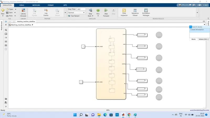
- Connect the chart block with; constant block for power and water inputs. Attached lamps to observe ON and OFF conition.
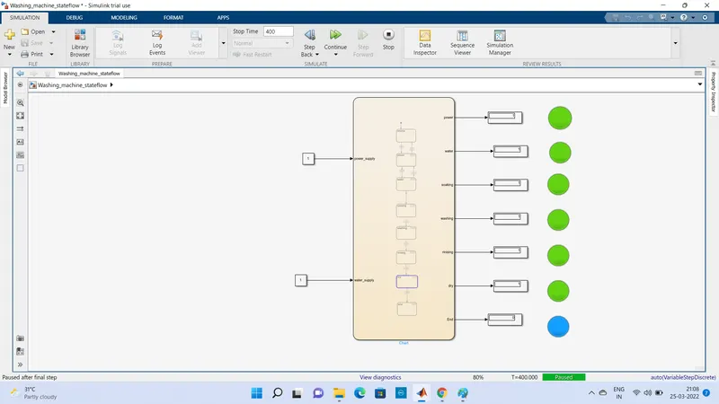
- A simulink model for operating the washing machine according to given condition is shown below -
- Control Logic structure -
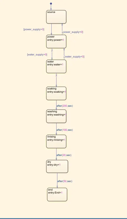
1. In the above control logic first junction is created with 2 conditins for power supply, one is when power supply available (power_supply>0) and second without power supply (power_supply<0). If the power supply at entry is 1 or ON the machine will get activated and the start next process for
2. Next 2 power supply state is created with 2 states with one for if power ON (power>0) and another of power OFF (power<0).
3. After the power supply state next was to select the state for water Two water supply states are created with 2 stated one for if water supply is ON (water>0) & another for power OFF (water<0).
4. Next four operation states have been crearted in flow order soaking, washing, rinising, drying with their time of operation as 200 sec. for a soak, 100 sec. for wash, 20 sec. for rinse and 50 sec. for entry and exit conditions of the states are kept as 1 because of the contineous operations of the process of the washing machine.
5. After finishing all the sets of operation the power supply is changed to state power = 0 which leads to shut off the machine.
Symbole pane -
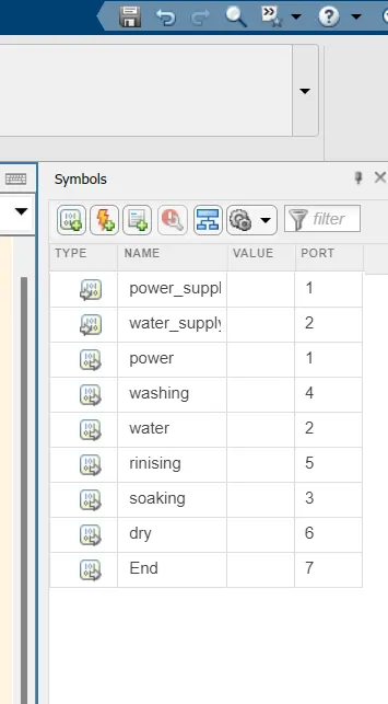
Here power_supply and water_supply are input ports
Power, washing, water, rinising, soaking, dry are output port.
Flow Chart -
After event creation flow chart is generated using some blocks from the library and thier connections are done as mention below
A constant block is used to supply the power and water and connected respective ports.
The display block is connected with each output of states of operation.
The lamp block is dragged from the simulink dashboard category to represent the LED for various operation performance evaluation.
These lamp block is connected to the respective output port in the chart.
When the operation is ON it is represented by green colour indication in a lamp when the output and viceversa for OFF is indicated by red colour when output is 0.
LED Indicators :-



When process off (0) When process run (1) End of process
Process wise indication of Lamp-
1. When Power_Supply is on and water supply is of
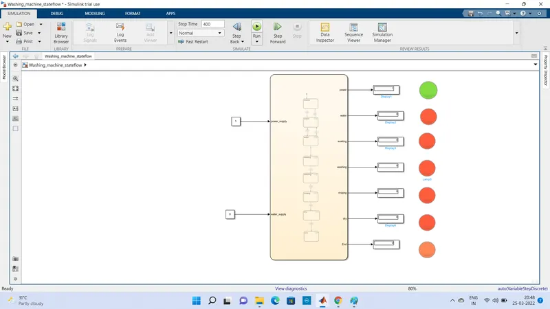
2. When power_supply and water_supply ON and run time 200 sec. (soak state)
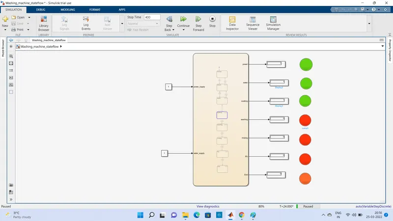
3. When power supply is on and Run time is 300 sec.(Wash state)
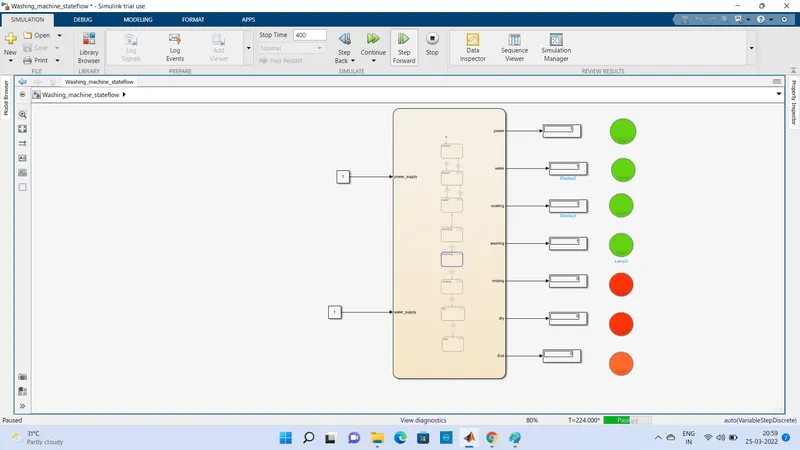
4. When power supply and water supply is on and run time is 320 sec.(Rinse state)
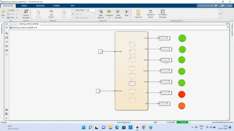
5. When power supply and water supply is on and run time is 350 sec.(Dryer state)
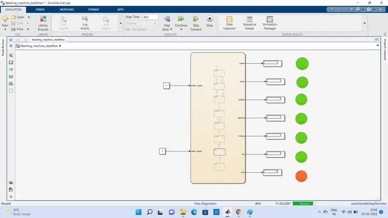
6. When power supply and water supply is on and run time is 400 sec.(end state)
Conclusion :-
From above sytem we study the different states of washing machine and how the state flow works with given inputs and show the indication when process is complited.
2. Make a Simulink chart for the “Gear shift” logic as per below conditions:
Speed Range(kmph) Gear
0 to 15 1
16 to 25 2
26 to 40 3
41 to 60 4
Above 61 5
Aim - Crete a state flow for gear shift and vary the speed as input and obtain the output as a gear number
Objective -
Make a Simulink chart for the “Gear shift” logic as per below conditions:
Speed Range(kmph) Gear
0 to 15 1
16 to 25 2
26 to 40 3
41 to 60 4
Above 61 5
What is gear Box -
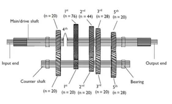
The gearbox is a mechanical device used to increase the output torque or to change the speed (RPM) of a motor. The shaft of the motor is connected to one end of the gearbox and through the internal configuration of gears of a gearbox, provides a given output torque and speed determined by the gear ratio. A manual transmission requires the driver to operate the gear stick and clutch in order to change gears (unlike an automatic transmission or semi-automatic transmission, where one (typically the clutch) or both of these functions are automated). Most manual transmissions for cars allow the driver to select any gear ratio at any time, for example shifting from 2nd to 4th gear, or 5th to 3rd gear. However, sequential manual transmissions, which are commonly used in motorcycles and racing cars, only allow the driver to select the next-higher or next-lower gear.
In a vehicle with a manual transmission, the flywheel is attached to the engine's crankshaft, therefore rotating at engine speed. A clutch sits between the flywheel and the transmission input shaft, controlling whether the transmission is connected to the engine (clutch engaged- the clutch pedal is not being pressed) or not connected to the engine (clutch disengaged- the clutch pedal is being pressed down). When the engine is running and the clutch is engaged (i.e., clutch pedal up), the flywheel spins the clutch plate and hence the transmission.
The design of most manual transmissions for cars is that gear ratios are selected by locking selected gear pairs to the output shaft inside the transmission. This is a fundamental difference compared with a typical hydraulic automatic transmission, which uses an epicyclic (planetary) design, and a hydraulic torque converter. An automatic transmission that allows the driver to control the gear selection is called a manumatic transmission, and is not considered a manual transmission. Some automatic transmissions are based on the mechanical build and internal design of a manual transmission but have added components (such as computer-controlled actuators and sensors) which automatically control the timing and speed of the gear shifts and clutch this design is typically called an automated manual transmission or sometimes a clutchless manual transmission.
Working -
With a manual transmission, the driver has to select the proper gear and engage or disengage the clutch. The transmission uses a flywheel, pressure plate and clutch to engage and disengage the engine from the transmission.
The flywheel and pressure plate are connected to the engine. The clutch is sandwiched between them and is splined to the transmission input shaft. The term push in the clutch means to release the pressure plate, which disengages the clutch from the engine. Every time you make a shift, you have to push in the clutch first.
Stepwise Procedure -
- First create a chart block for defining the state flow as per given condition
- if speed is less than or equal to 0, the flow is terminated and gear 0 is at junction else 1 is carry forwarded
- If speed is greater than 0 and less than or equal to 15, the flow is terminated and gear 1 is
- If speed is greater than 15 and less than or equal to 25, the flow is terminated and gear 2 is
- Speed is greater than 25 and less than or equal to 40, the flow is terminated and gear 3 is
- Speed is greater than 40 and less than or equal to 60, the flow is terminate and gear is 4
- Speed is greater than 60, the flow is terminated and gear 5 is
Control Logic structure -
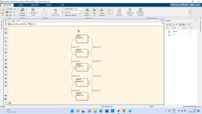
In the above logic control first - the default transmission is draged from the browser menu.
Five gear state is created with the state condition of gear G1,G2,G3,G4,G5 and there transition is connected with speed range condition as shown in image.
The transition conditions for gear shift is decided as
speed>15 shift to G2
speed>25 shift to G3
speed >40 shift to G4
speed>50 shift to G5
similarly reverse direction speed
<60 speed shift to G4
<40 speed shift to G3
<25 speed shift to G2
<15 speed shift to G1
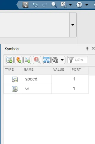
Symbol Pane -
Flow Chart -
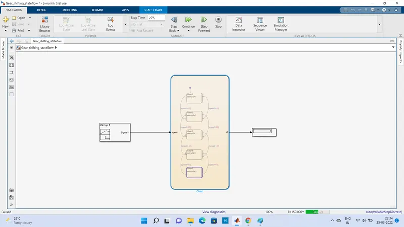
After event creation flow chart is generated using some blocks from the library and thier connection done as mention below -
A signal builder block is connected to speed input, this block generate the various speed with rispect to time as given command. Display block is connecte with G Port to show the gear position during simulation.
Results -
When we change the speed with time (using signal builder block) the gear position change from 1 to 5 and 5 to 1 for simulation run time 275 sec.