Project
Project - 1
Aim - Carry out a system-level simulation of an all-terrain vehicle.
Key Words Used - Lookup table, CVT, Dashboard, Baja ATV.
Objective -
- Study the Baja ATV model without dashboard.
- Study the Baja ATV model with dashboard.
- Study the Baja ATV model using lookup table.
Itroduction -
What is ATV (All terrain vehicle) ?
An all-terrain vehicle (ATV), also known as a light utility vehicle (LUV),a quad bike, or simply a quad, as defined by the American National Standards Institute (ANSI); is a vehicle that travels on low-pressure tires, with a seat that is straddled by the operator, along with handlebars for steering control. As the name implies, it is designed to handle a wider variety of terrain than most other vehicles. Although it is a street-legal vehicle in some countries, it is not street-legal within most states, territories and provinces of Australia, the United States or Canada.
By the current ANSI definition, ATVs are intended for use by a single operator, although some companies have developed ATVs intended for use by the operator and one passenger. These ATVs are referred to as tandem ATVs.
The rider sits on and operates these vehicles like a motorcycle, but the extra wheels give more stability at slower speeds. Although most are equipped with three or four wheels, six-wheel models exists and existed historically for specialized applications. Multiple-user analogues with side-by-side seating are called utility terrain vehicles (UTVs) or side-by-sides to distinguish the classes of vehicle. Both classes tend to have similar powertrain parts. Engine sizes of ATVs currently for sale in the United States (as of 2008 products) range from 49 to 1,000 cc (3.0 to 61 cu in).
What is CVT (continious variable transmision) and how it works?
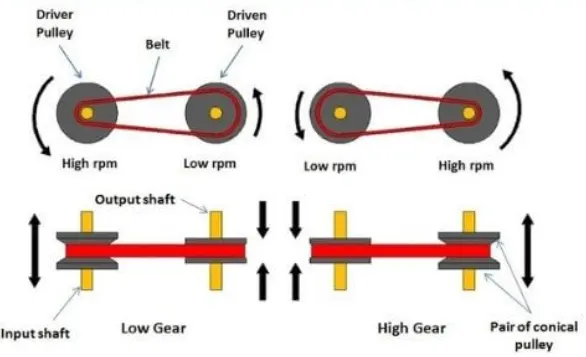
A continuously variable transmission (CVT) is an automatic transmission that can change seamlessly through a continuous range of gear ratios. This contrasts with other transmissions that provide a limited number of gear ratios in fixed steps. The flexibility of a CVT with suitable control may allow the engine to operate at a constant RPM while the vehicle moves at varying speeds.
CVTs are used in automobiles, tractors, motor scooters, snowmobiles, bicycles and earthmoving equipment.
The most common type of CVT uses two pulleys connected by a belt or chain; however, several other designs have also been used at times.
How it works -
A CVT gearbox has a relatively simple arrangement of two cone-shaped pulleys with a V-shaped drive belt connecting them. One pulley is attached to the engine, while the other is joined to the wheels. When you press the accelerator, the engine revs and the cone moves according to the amount of power asked for. The other cone adjusts accordingly so that the drive belt maintains the same tension, and this is what determines how the car accelerates.
As the two cones move independently, that means there are no set gear ratios as you would find in a conventional auto or manual, so a CVT is, in effect, a single-speed unit with infinite gear ratios available. That also explains why CVT-equipped cars have a familiar high-revving character, because engine revs aren't related to wheel speed.
Study of Given ATV model -
Study 1 -
simscape model of ATV -
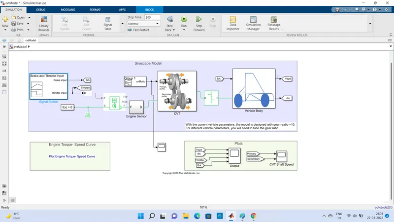
Diagram -1 of simscape model of ATV.
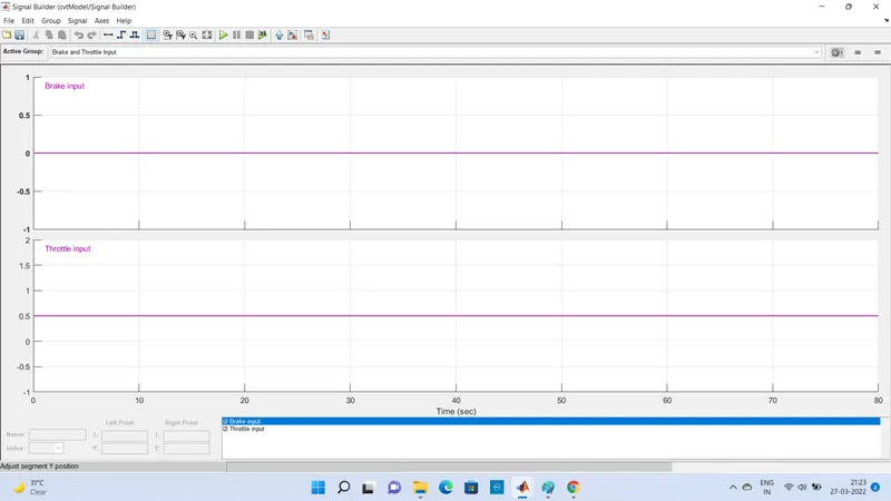
By using simulink model of CVT consist of signal builder, Generic engine, Motion sensor, vehicle transmission, vehicle body, and solver configration block etc. as shown in Diagram-1. Signal builder block is used to give brake input and throtle input signal 0 & 0.5 respectively. Below image shows the signal builder signal inputs.
Engine speed vs torque input -
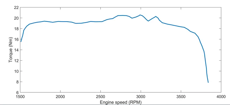
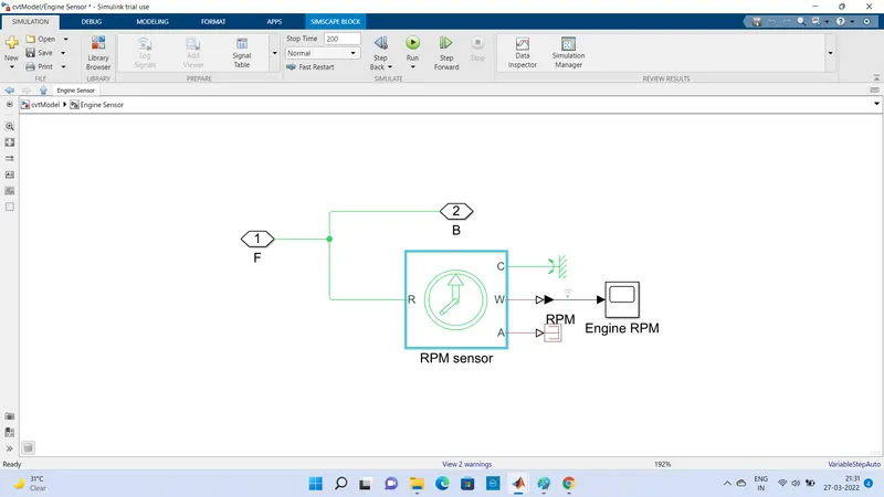
Generic Enginen Block is used as a power source, the initial engine speed is given as 1750 rpm. engine sensor subsystem block is used to measure the engine RPM, below image shows the Engine sensor subsystem diagram in which used angular motion sensor to sense engine RPM.
Engine crank shaft connected to the CVT system includes transmission block, input and output shaft inertia and motion sensor as shown in diagram 2.
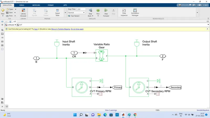
Diagram - 2 Block diagram of CVT sub system.
There are variable gear ratio block is used as a gear box, it has r port and b port. For r port signal builder of diferrent gear ratio is connected having initial gear ratio is 3.7 and last gear ratio is 0.7 and b port is connected with engine F port (crank shaft) having rpm 1750. The CVT has input shaft and output shaft, port F to port B connection is input shaft and port F to simple gear port B connection is output shaft. Rotational motion sensors is attached on input and output shaft i.e CVT primary and secondary shaft to measure the RPM of shaft. In rotational motion sensor one port (R) is a input siganl and C is Referance point rigidly attached to frame, W is angular velocity, A is angle change position outputs. Here we connected scope block to W to measure angular velocity of shaft. Two innertia block is used for inpur and output shaft.
After CVT subsystem block used simple gear box in that Follower and Base gear, gear ratio is 10.
The vehicle body subsystem includes vehicle body block, double drum brake and tyre as shown in diagram 3.
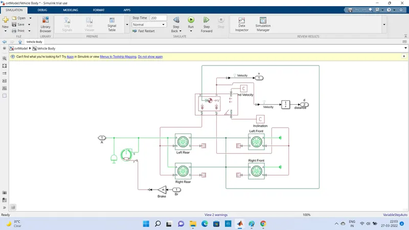
Diagram - 3 Vehicle Body subsystem.
Brake is used for all four wheels drum brake is used for all four wheels having brake arranged as two pivoted rigid shoes symmetrically installed inside or outside a drum and operated by one actuator. The actuator force causes the shoes to exert a friction torque on a shaft connected to the drum. Brake drum of Dia. 150mm, Actuator location radius 100mm, shoe bigining angle 5 deg. shoe span angle 120 deg. viscous coefficient of friction 0.01 N*M/(rad/sec.) Wheel specification as Rated verticle load 2060 N, Pick longitudnal force at rated load 1260 N, Slip at pick force at rated load (%) 5, roling radius 0.2921 m. Tyre inertia 0.01 kg*m^2, initial velocity 0 rpm. The wheel have 4 ports Port A is mechanical rotational conserving prots, Connection H is the mechanical translational conserving port for the wheel hub through which the thrust developed by the tire is applied to the vehicle. Connection N is a physical signal input port that applies the normal force acting on the tire. The force is considered positive if it acts downwards. Connection S is a physical signal output port that reports the tire slip.
Vehicle body represents a two-axle vehicle body in longitudinal motion. The block accounts for body mass, aerodynamic drag, road incline, and weight distribution between axles due to acceleration and road profile. The vehicle can have the same or a different number of wheels on each axle. Optionally include pitch and suspension dynamics or additional variable mass and inertia. The vehicle does not move vertically relative to the ground.
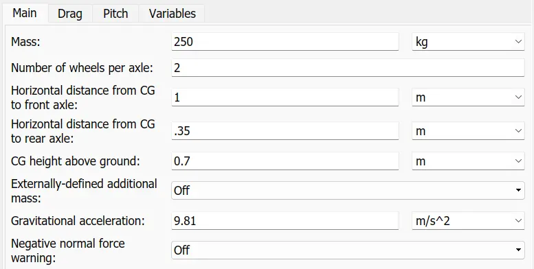
Connection H is the mechanical translational conserving port associated with the horizontal motion of the vehicle body. The resulting traction motion developed by tires should be connected to this port. Connections V, NF, and NR are physical signal output ports for vehicle velocity and front and rear normal wheel forces, respectively. Wheel forces are considered positive if acting downwards. Connections W and beta are physical signal input ports corresponding to headwind speed and road inclination angle, respectively. If variable mass is modeled, the physical signal input ports CG and M are exposed. CG accepts a two- element vector representing the x and y distance offsets from vehicle CG to additional load mass CG. M represents the additional mass. If both variable mass and pitch dynamics are included, the physical signal port J accepts the inertia of the additional mass about its own CG. Below image show parameters of vehicle body
Results -
Below graph shows the results of Throttle input, Brake, Displacement and velocity of vehicle.
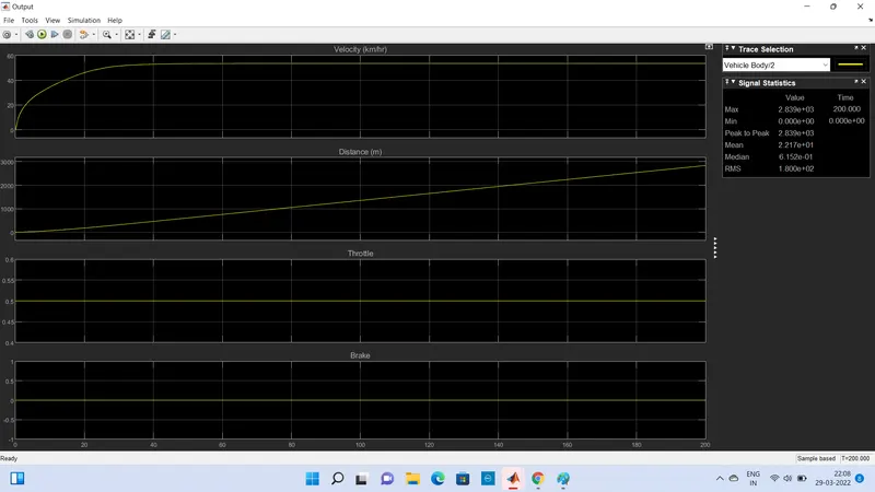
From above graph we conclude that Brake is 0, throttle input is 0.5, at this input conition Velocity of boy at initial is 0 and at 40 sec. 53.53 Km/Hr remains constant and distance travel is 2839 m in 200 sec. run time.
CVT Primary and scondary shaft RPM-
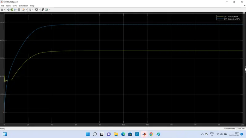
in above graph Yellow line show primary CVT RPM and Blue line shows secodary CVT RPM.
The primary RPM from above graph is 1662 at initial and 3415 RPM at 200 sec.
Where in Secodary CVT RPM initial value is 0 RPM and 4878 RPM at 200 sec.
Baja ATV model with Dashboard -
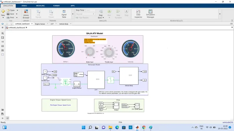
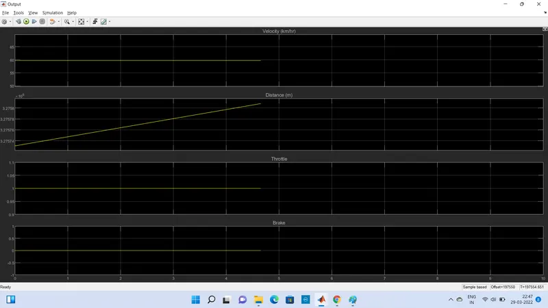
It is same model as shown priviously but here we see that we used dash board on which two knobs are provided for throttle and brake input 1 and 0 respectively, and RPM at secodary shaft and velocity is shown on dashboard ny analog meter. Runing time for this simulation is infanite. Reluts in graphical form is as shown below.
RPM Results
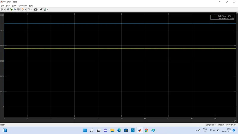
Above graph shows the Primary and secodary CVT RPM, Yellow line shows primary CVT RPM and Blue line shows Secondary CVT RPM.
Study -3
ATV CVT Model using Lookup table
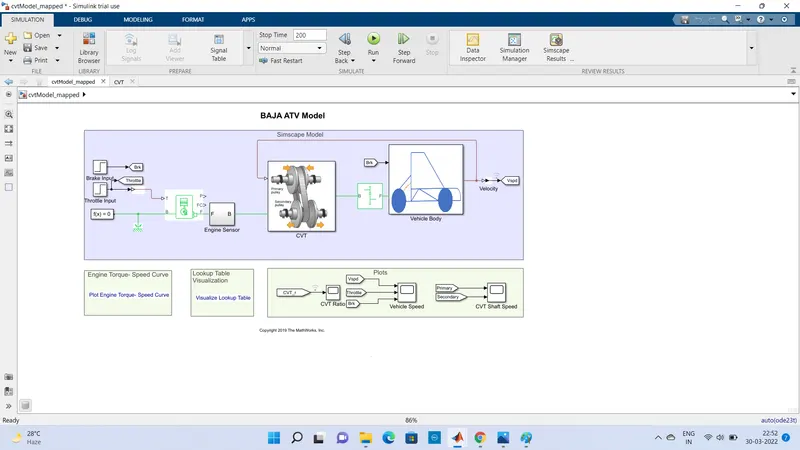
This model is same as privious on but here we used step signal for Brake and throttle input, the value of brake is 0 and the value of throttle is 0.3 initial and 1 final value.
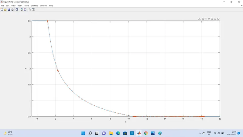
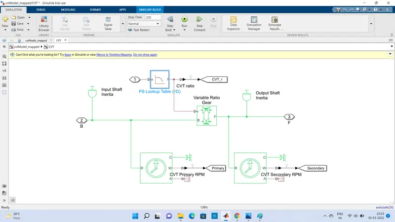
Also the main difference is that here we used lookup table to store the data of Variable gear ratio as shown in image below
Below image shows CVT Subsytem in which we use Lookup table for variable gear ratio -
Results -
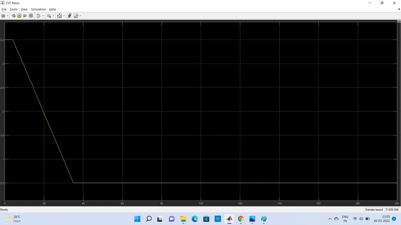
Above graph shows the variable gear ratios with respect to time initial gear ratio is 3.5 and decrease it gradualy to 0.5 and remains constant.
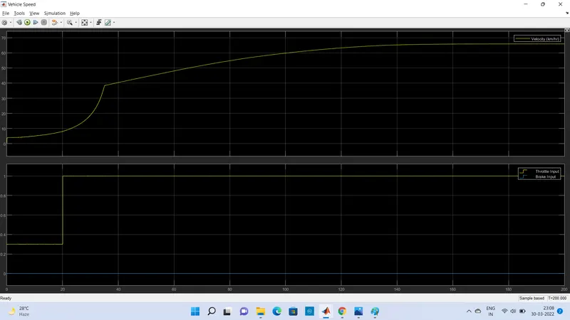
In above graph first graph is ploted results of vehicle velocity and second graph shows the throttle and brake inputs by yellow and blue line respectively.
As we seen the initial velocity of vehicle is zero to he throttle of 0.3 as we increase the throttle velocity of vehicle is also increase. At 1 throttle the velocity reaches to 65.90 KM/H.
CVT RPM
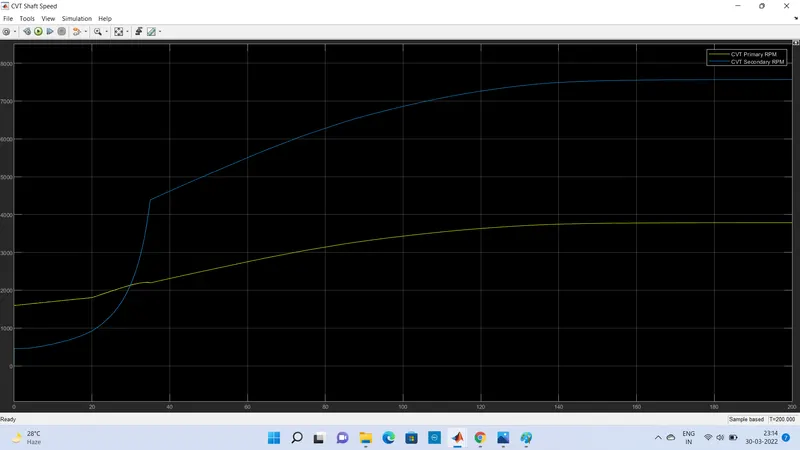
Above Graph shows the RPM of primary and secodary shaft. As seen in graph the the initial value of primary shaft is 1597 RPM that time seconary shaft RPM is 0. When throttle increase the speed of vehicle is get increase, at primary shaft 3784 RPM valur of secondary shaft 7568 RPM.
Conclusion - Thus we have succesfuly analysed different model of BAJA ATV with CVT and record the outputd (CVT Shaft velocity and CVT Shaft RPM ) with respect to variation input throttle and brake.