Week -2
- Doorbell Simulink -
- Aim -
To make simulink model of doorbell using solenoid block.
- Objective -
Create a simulation of doorbell and study the physical movement of the plunger.
- Working of doorbell system -
1. When we push the doorbell switch the circuit get closed.
2. Current flow in circuit, when curren flow through the solenoid the EMF generate in specific area, which leads to plunger drawn in.
3. Plunger hit the bell and produce a sound.
4. After releasing button circuit open and plunger move back to its home position.
Blocks used in simulink diagram -
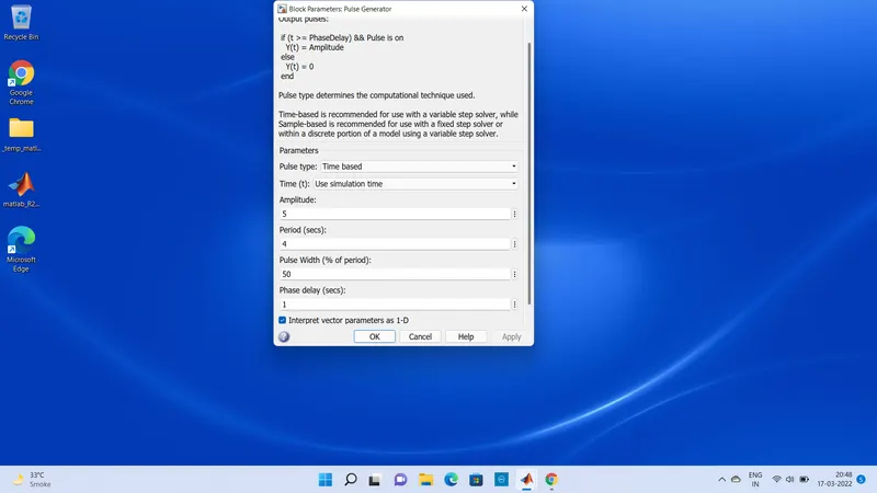
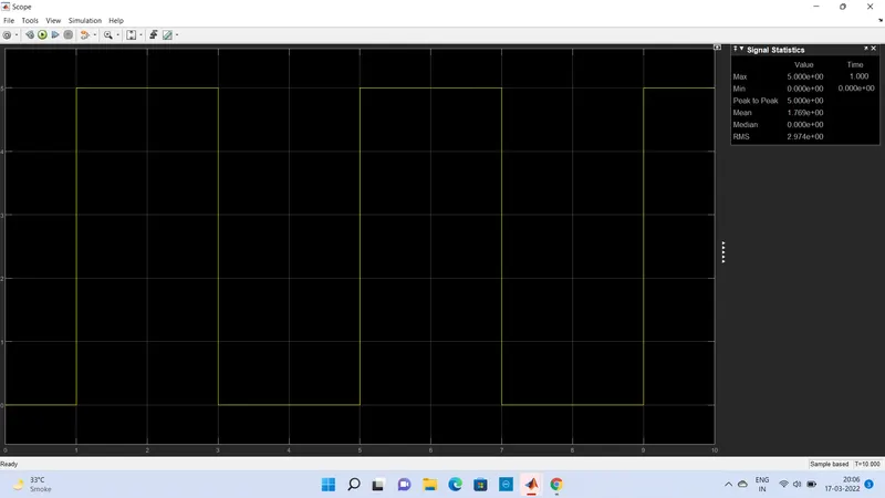
1. Pulse generator - It generate the square block wave up to the given time (2sec.) and amplititude (5).
2. PS Simulink convertor - It converts input physical signal to the output simulink signal
3. Battery - It is a power source for electrical system, here we used 12 volt battery. It has two terminal +ve and -ve.
4 Switch - Switch is controlled by an external physical signal. If the external physical signal Ps is greater than the threshold the switch is close otherwise the switch is open.
5 Electrical reference - It is a ground signal for electrical system.
6 Solenoid - Solenoid is a electromechanical device, it consist windings of coil and plunger, when the current flow through the winding it produce EMF which leads to plunger in.
7. Mechanical Translational reference - It is use to connect mechanical translational ports that are rigidly affixed to the frame or ground.
8. Translational motion sensor - This block measure the velocity or displacement in mechanical translational network. The physical signal port V and P report the velocity and position respectively of port R relative to port C.
9. Simulink to PS convert - It converts input simulation signal to physical out put signal.
10. Scope - It shows the result in graphical form.
- Pulse Generator Result -
Result -
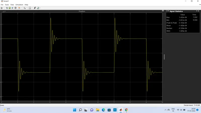
From Aboe graphical diagram we conclude that the plunger at zero position initialy when switch get closed it movment occurse on 1 sec maximum and goes down after that, return to its home position.
# use thermistor to sense the temperature of heater -
- Aim -
- Use a thermistor to sense the temperature of a heater & turn on or turn off.
- Objective -
- To study the fan on and off time with respect to given conition.
- Condition -
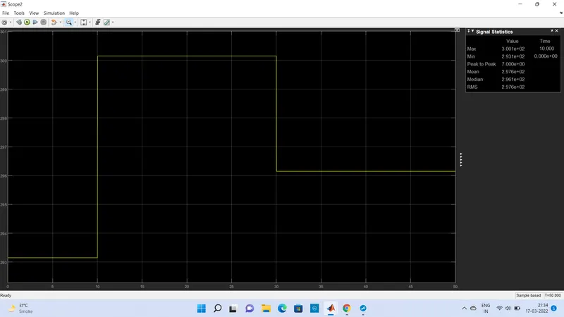
- Temperature source - 20 deg. for 0 to 10 sec. 27 deg. for 10 to 30 sec. and 23 deg. for30-50 sec.
- condition - When temp. is above 25 deg. then fan on otherwise off.
- Blocks used in model -
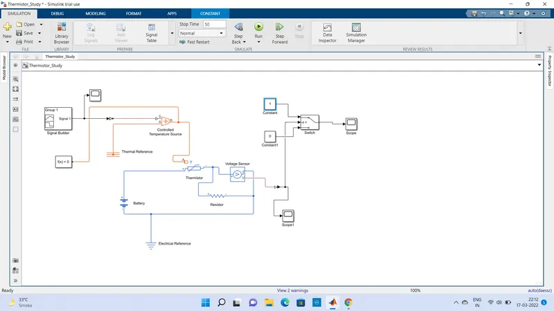
- Signal Buillder - This block is used to build the signal of temp. with respect to gien time. i.e 293.15 K. for 0 to 10 Sec. and others.
- Control Temp. source -
- This block represent an ideal energy source in a thermal network that can maintain a controlle temp. difference regardless of the heat flow rate. The temp. difference is set by the physical signal port s.
- Thermal reference -
- This block represent a reference point in a thermal netwrok where the temp. is equal to absolute zero.
- Thermistor -
- This block represent an Negative coefficient temp. (NTC) thermistor using the B-Patameter equation.
- Battery -
- This block is used as a power sourse for electrical system.
- Voltage sensor -
- The block represents an ideal voltage sensor, that is, a device that converts voltage measured between any electrical connection into a physical signal to the voltage.
- Electrical reference -
- Electrical reference block is used to ground for electrical system.
- Resistor -
- The block models a resistor with opetional tolerence, operational limit, fault and thermal noise modeling.
- Switch -
- This block is used as a switch which operates on given threshold voltage. Voltage pass through input 1 when satisfies the selected criterion; otherwise, pass through input 3.Three shold voltage for 25 deg. is 0.01197 V.
- Constant -
- This block is used for constant value.
- Scope -
- This block shows the graphical presentation of respective block results.
Block Diagram -
Model Explanation -
A signal builder generates the signal of temperature and provides to the thermister through controll temperature source. The condition of temp. source is given in signal builder block. Below given i mage shows the signal with respect to time.
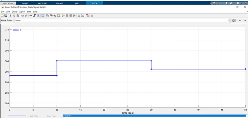
The condition of the temp. source is defien inside the above window. The sample time is taken as 10 sec. and simulation run time taken as a 50 sec.
Battery and resistor connected in the thermistor circuit. A voltage sensor given across this resistor to measure voltage change during different temp. inputs. The resistance of resistor can be set to any value but it not change once the threshold voltage found. The threshold voltage given as 25 deg. (298.15K) and the corosponding voltage over the resistor found out, through a display connected to voltage sensor. The output voltage given to the switch, where switch has given the threshold voltage at input 2. when the voltage reaches to threshold value switch get close and circuite is completed.
Results -
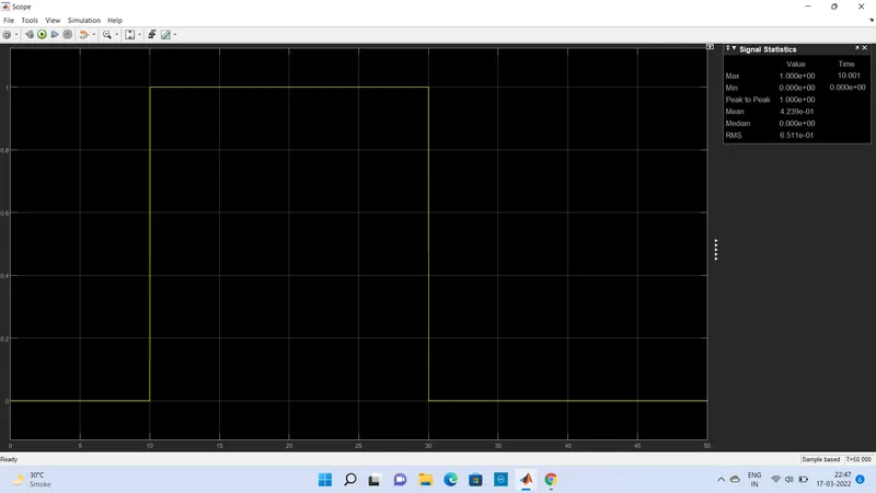
From above graph we conclude that the temperature at 0 to 10 second is below threshold value causing switch is off but at 10 to 30 sec. temp. reaches to its threshold limit then the switch get on and circuit completed and for nexr 30 to 50 sec. it again goes below threshold value then switch get open and fan off.