Week 8 Challenge
Aim : To calculate the centrifugal force for the bridge by using following data.
Given data :
- Width of the carriage way is 7 m
- Span of bridge is 12 m
- Design speed of the more 75 km/hour
- Radius of curvature in the bridge is 3 m
- Bridge is subjected to a live load of class 70 R tracked vehicle
Theory :
The moving of a vehicle in a curve produces an outward pushing force from the bridge which exerts a loads on the structural elements of the bridge is called the centrifugal loads
For calculating water current forces IRC 6:2000 is used.
Calculation:
C = ( W x V2 ) / 127 x R
Where , C is centrifugal force
V is the design speed
R is the radius of the curvature
W is the live load
C = ( 70 x 752 ) / 127 x 3
C = 1033.464 KN
Aim : To prepare the model in a STAAD Pro and perform the analysis and justify with the results.
Theory : The general steps to be create a STAAD Pro model is given below,
Step 1 : Create the nodes by using the nodes cursor.
Step 2 : Joining the nodes by using the respective beam plate cursor.
Step 3 : Supports given to the nodes whether its pinned or fixed or any other custom supports
Step 4 : specifications given to the respective beams plates Step 5 : Assign the dead load as per calculation
Step 6 : Save the model and perform the analysis
Step 7 : The results are obtained and discuss with the results Step 8: Take the print out of report of necessary results.
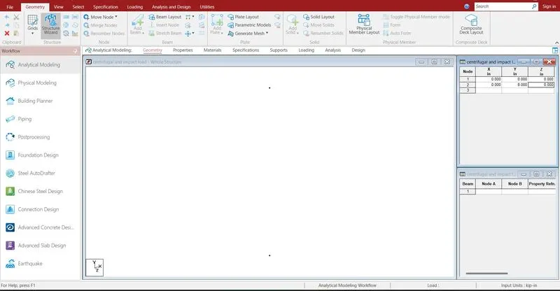
Creating the nodes by using node cursor.
Open the STAAD Pro window > Select > Node cursor > enter the value with respect to X Y Z axis > click enter
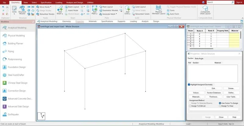
Join the nodes by using beam cursor.
Select > beam cursor > join by dragging the mouse or enter the node numbers > click enter
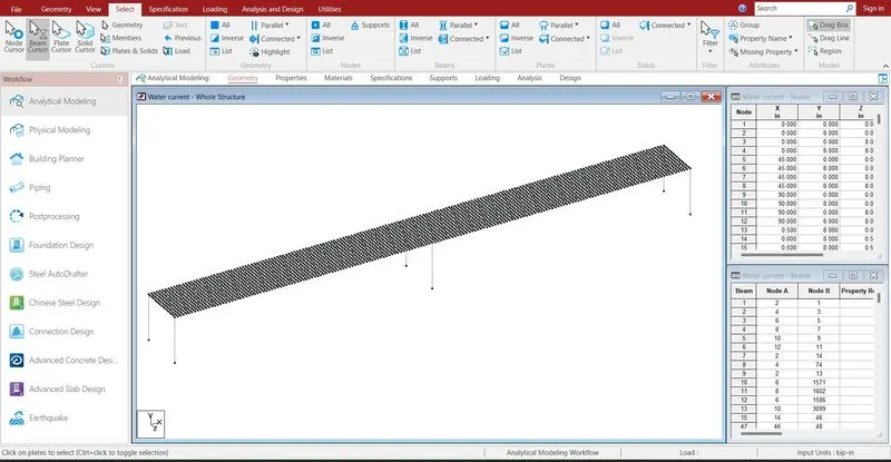
model has been prepared.
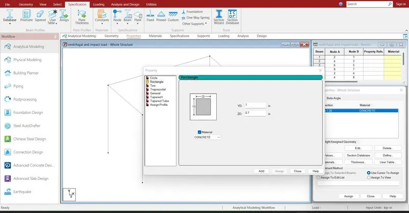
Assigning the properties to the beam .
Specification > Prismatic > Rectangle > enter dimensions > select the beam > assign the properties to selected beams.
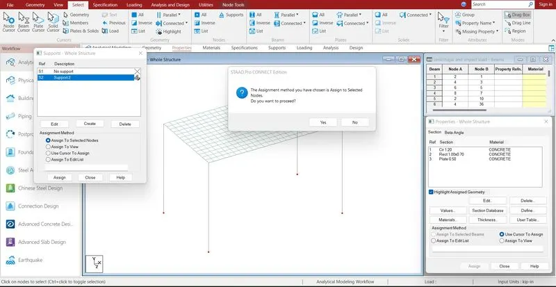
Supports are given to the respective nodes.
Specifications > Supports > select the supports > click enter

Properties are assigned.
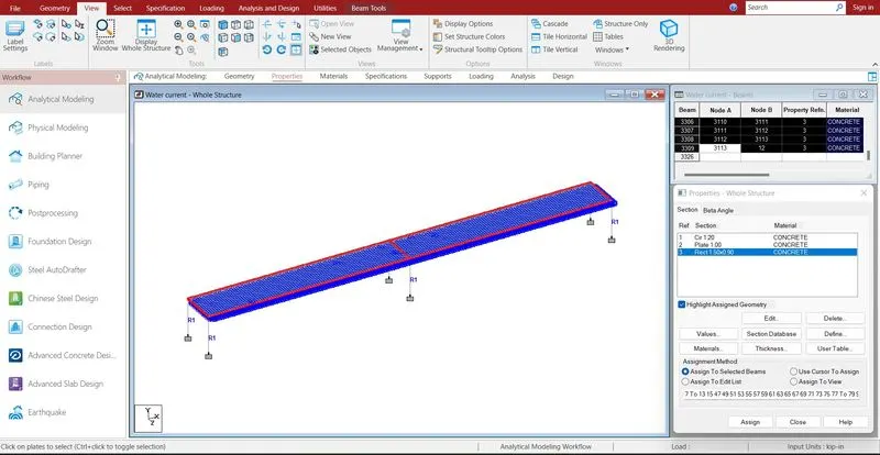
girder properties are assigned.
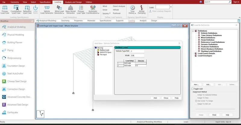
Defining the load cases .
Definition > Vehicle definition > define load > Add
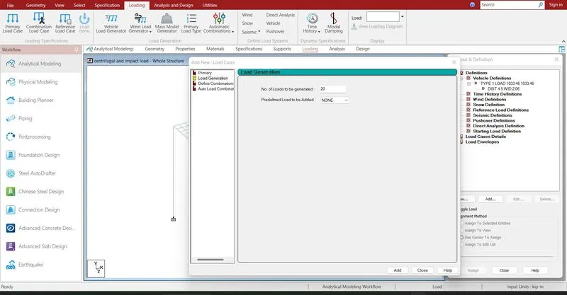
Loadcase > add > load generation > add
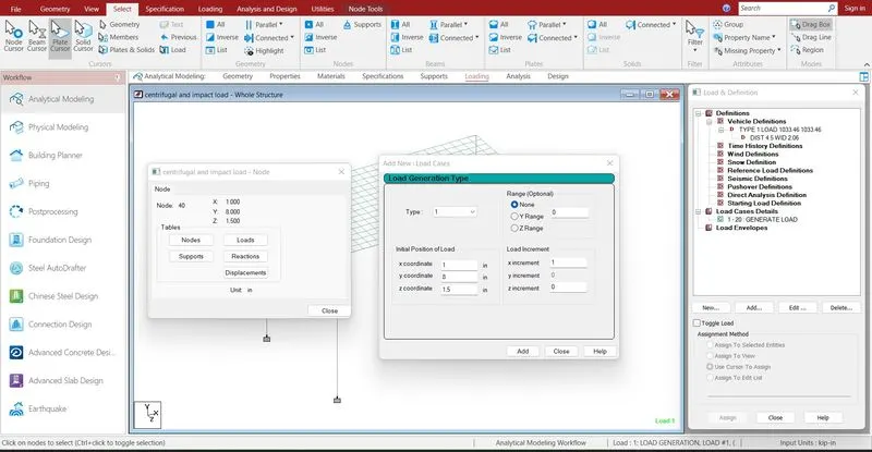
Add > give the ranges > add
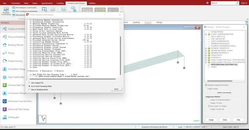
Run analysis > go to post processing mode > Results
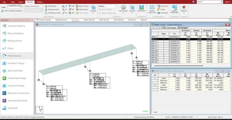
The reactions are generated at the end of the nodes .the reaction value is 2066.92 KN
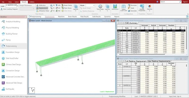
- The maximum deflection in X direction is 7.204 mm
- The minimum deflection in X direction is -7.949 mm
- The maximum deflection in Y direction is 0.005 mm
- The minimum deflection in Y direction is -76.961 mm
- The maximum deflection in Z direction is 3.78 mm
- The minimum deflection in Z direction is -4.72mm
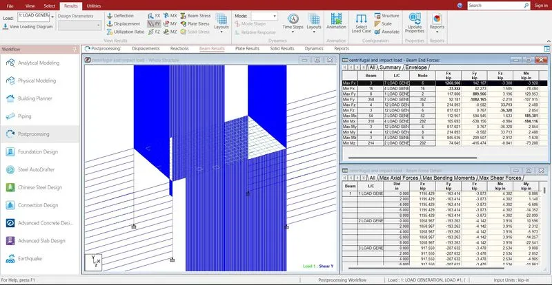
- The maximum shear force in X direction is 1260.506 KN
- The minimum shear force in X direction is -33.22 KN
- The maximum shear force in Y direction is 889.566 KN
- The minimum shear force in Y direction is -1082.165 KN
- The maximum shear force in Z direction is 33.713 KN
- The minimum shear force in Z direction is -36.328 KN
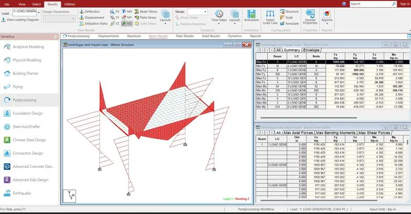
- The maximum bending moment in X direction is 185.381 KN-m
- The minimum bending moment in X direction is -184.116 KN-m
- The maximum bending moment in Y direction is 205.405 KN-m
- The minimum bending moment in Y direction is -170.305 KN-m
- The maximum bending moment in Z direction is 1136.796 KN-m
- The minimum bending moment in Z direction is -1184.71 KN-m
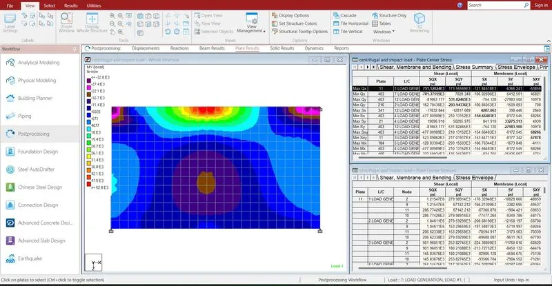
The max shear stress in x is 207.107 kilo newton square mm
The min shear stress in x is -143.946 kilo newton square mm
- Reports are taken printout which ever is necessary by using report
- In the report option we obtain the results of section forces, displacement, reactions, plate
- The exact report is to be taken further move to design