Week 3 Challenge
Aim : To apply the IRS railway loads and model in Staad pro and perform the results and justify.
Given data :
Width of bridge deck – 26 m
Span of the bridge - 25 m
Pier height – 10 m
Theory : Live Load as per IRS is different for different broad gauges.
Here, for given problem am applying a IRS Metro rail loading. For the live load consideration the IRS gives a guide lines. For Railway loading we are using a IRS Indian Railway Standards .According to that we have to follow the rules and apply the load.
Explanation : In the IRS loading totally 4 axle loads. Width of the spacing is 1.8m.
4 axle load consideration and spacing between the axle are given below.
|
Axle load (KN) |
Spacing (m) |
|
170 |
- |
|
170 |
2.2 |
|
170 |
12.4 |
|
170 |
2.2 |
Aim : To prepare the model in a STAAD Pro and perform the analysis and justify with the results.
Theory : The general steps to be create a STAAD Pro model is given below,
Step 1 : Create the nodes by using the nodes cursor.
Step 2 : Joining the nodes by using the respective beam plate cursor.
Step 3 : Supports given to the nodes whether its pinned or fixed or any other custom supports
Step 4 : specifications given to the respective beams plates
Step 5 : Assign the live load as per calculation
Step 6 : Save the model and perform the analysis
Step 7 : The results are obtained and discuss with the results
Step 8: Take the print out of report of necessary results.
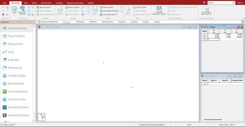
Creating the nodes by using node cursor.
Open the STAAD Pro window > Select > Node cursor > enter the value with respect to X Y Z axis > click enter.
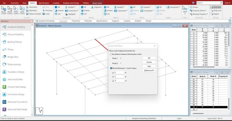
Join the nodes by using beam cursor and by using translational repeat command model has been created.
Select > beam cursor > join by dragging the mouse or enter the node numbers > click enter
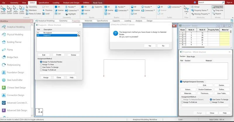
Supports are given to the respective nodes.
Specifications > Supports > select the supports > click enter
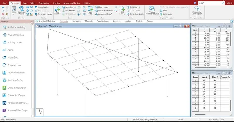
To draw the deck slab plate to the model.
geometry > add plate > draw with respect to the nodes.
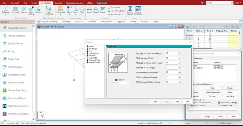
Defining and Assigning the properties to the cross girders and main girders .
Specification > Prismatic > Rectangle > enter dimensions > select the beam > assign the properties to selected beams.
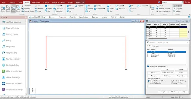
Assigning properties to the pier.
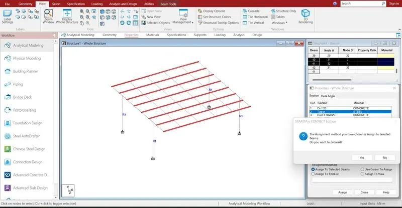
Assingning properties to the cross girder.
Assingning properties to the main girder.
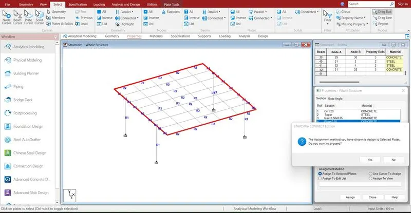
Assingning properties to the Deck slab.
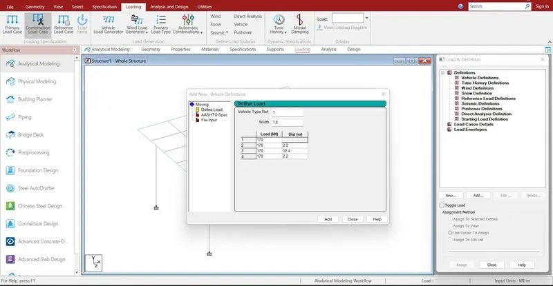
Defining the load cases .
Loading > definition > vehicle definition > Add > define load
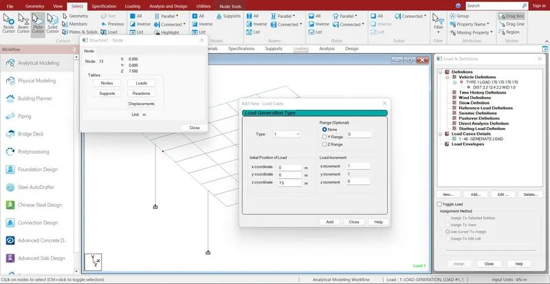
Load case > Add > load generation > add > give the range value to be load start and en of the bridge.
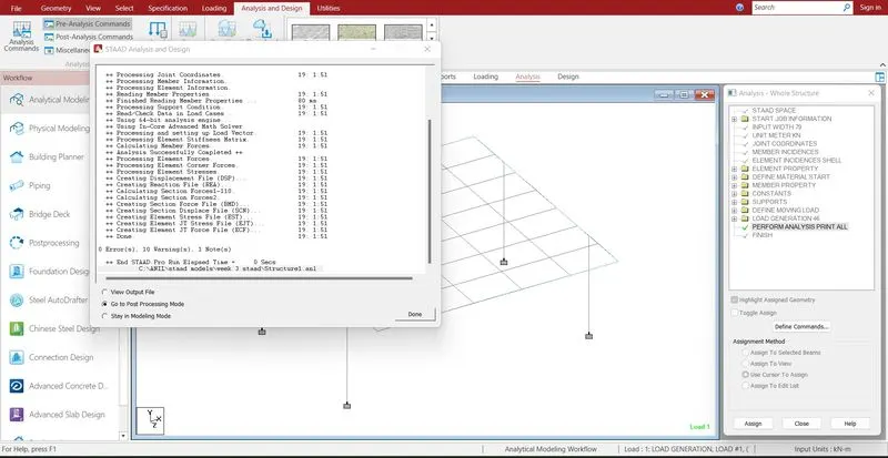
Run analysis > go to post processing mode > Results
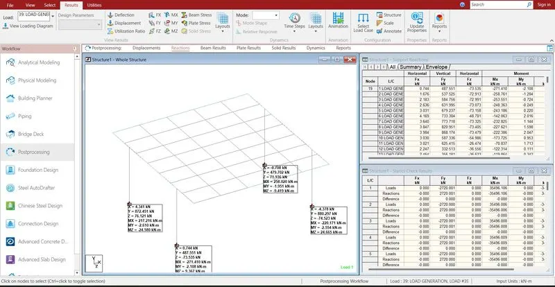
The reactions are generated at the supports which we are given .
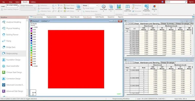
The base pressure and shear X shear Y are almost zero in this condition.
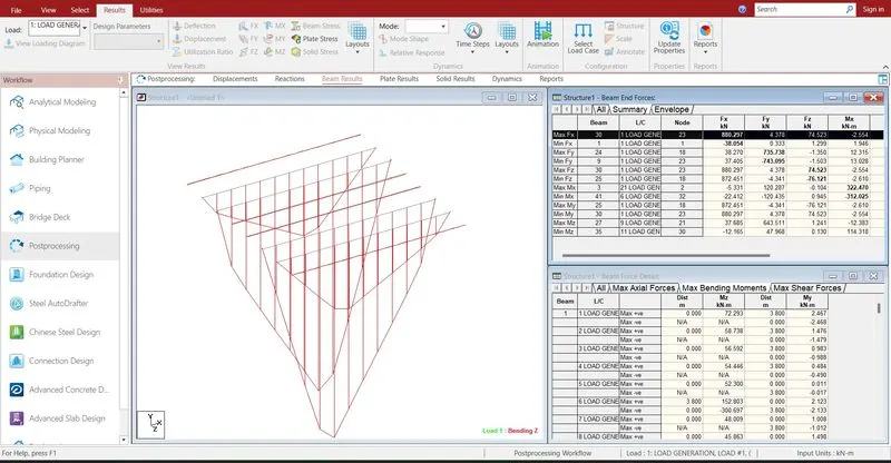
- The bending moment diagram for the girders is analysed.
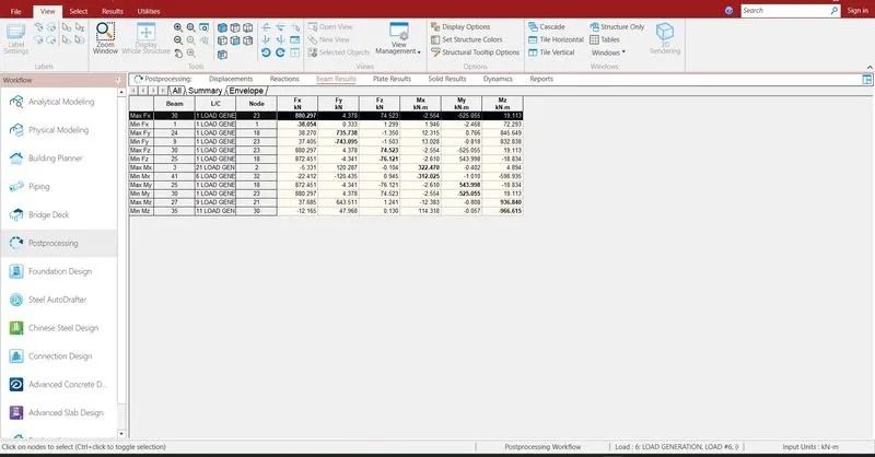
- The maximum Bending Moment at the Z axis is 936.84 KN.
- The minimum Bending Moment at the Z axis is -966.615 KN.
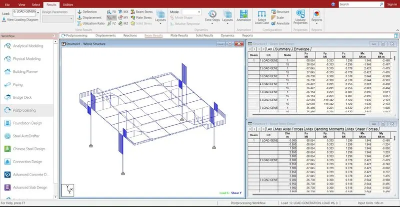
- The maximum Shear force at the Y axis is 735.738 KN.
- The maximum Shear force at the Y axis is -743.049 KN.