Week 1 Challenge
Aim : To calculate the dead load on a box girder bridge of span 12 m.
Given data :
Width of bridge deck – 10.2 m
Span of the bridge - 12 m
Pier size – 2.5 m dia
The seismic zone – zone 4
Wind speed – 47 km/hr
Location – Bengal
Theory : Dead Load as per IS 875 – Part 1, the unit weight of materials are different from each other. Some of them are listed below.
- Reinforced cement concrete – 25 KN/m^3
- Plain cement concrete – 24 KN/m^3
Self weight of structural elements .
To calculate the load the formula is given by
Self weight (Load) KN/m, = cross section area of structural element x unit weight
The box girder is divided into 11 basic shapes for make easier to calculate the area, By using area we can calculate the dead load.
Note : The area of the different shapes of the geometry are calculated by using area formulas are listed below.
- Area of triangle = 0.5 x base x height
- Area of rectangle = length x breadth
- Area of parallelogram = base x height
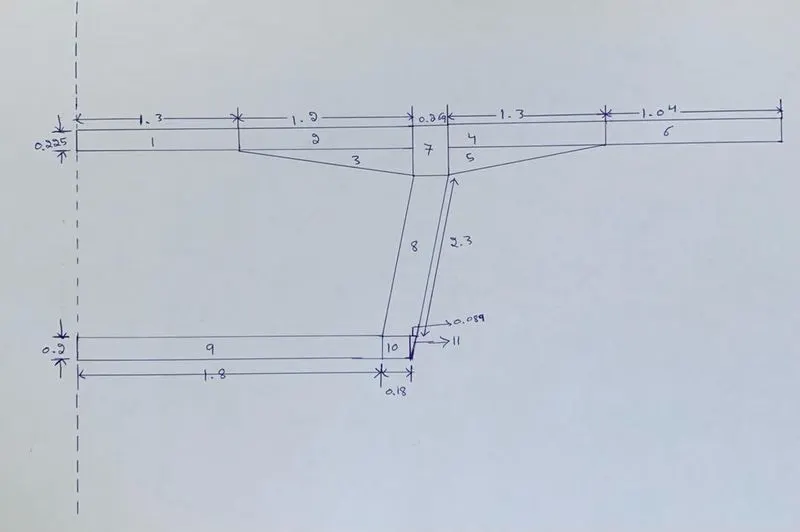
|
Si No |
Shape |
Length, m |
Breadth, m |
Height, m |
Area, square meters |
Unit weight of concrete, KN/m^3 |
Load, KN/m |
|
1 |
Rectangle |
1.3 |
0.225 |
- |
0.29 |
25 |
7.25 |
|
2 |
Rectangle |
1.2 |
0.225 |
- |
0.27 |
25 |
6.75 |
|
3 |
Triangle |
- |
0.125 |
1.2 |
0.075 |
25 |
1.875 |
|
4 |
Rectangle |
1.3 |
0.225 |
- |
0.29 |
25 |
7.25 |
|
5 |
Triangle |
- |
0.125 |
1.3 |
0.08 |
25 |
2 |
|
6 |
Rectangle |
1.04 |
0.225 |
- |
0.234 |
25 |
5.85 |
|
7 |
Rectangle |
0.350 |
0.269 |
- |
0.094 |
25 |
2.35 |
|
8 |
Parallelogram |
- |
0.269 |
2.3 |
0.61 |
25 |
15.25 |
|
9 |
Rectangle |
1.8 |
0.2 |
- |
0.36 |
25 |
9 |
|
10 |
Rectangle |
0.18 |
0.2 |
- |
0.036 |
25 |
0.9 |
|
11 |
Triangle |
- |
0.08 |
0.2 |
0.008 |
25 |
0.2 |
|
Total Load |
= 58.675 |
||||||
The given structure is symmetrical axis hence the total load is 58.675 x 2 = 117.35 KN.
Aim : To prepare the model in a STAAD Pro and perform the analysis and justify with the results.
Theory : The general steps to be create a STAAD Pro model is given below,
Step 1 : Create the nodes by using the nodes cursor.
Step 2 : Joining the nodes by using the respective beam plate cursor.
Step 3 : Supports given to the nodes whether its pinned or fixed or any other custom supports
Step 4 : specifications given to the respective beams plates
Step 5 : Assign the dead load as per calculation
Step 6 : Save the model and perform the analysis
Step 7 : The results are obtained and discuss with the results
Step 8: Take the print out of report of necessary results.
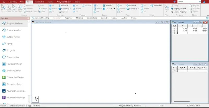
Creating the nodes by using node cursor.
Open the STAAD Pro window > Select > Node cursor > enter the value with respect to X Y Z axis > click enter.
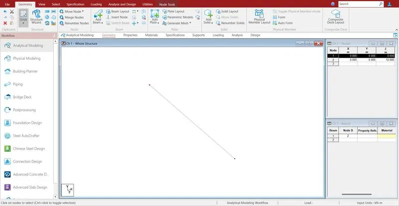
Join the nodes by using beam cursor.
Select > beam cursor > join by dragging the mouse or enter the node numbers > click enter
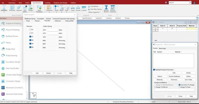
Moments released with respect to support which is to the given supports.
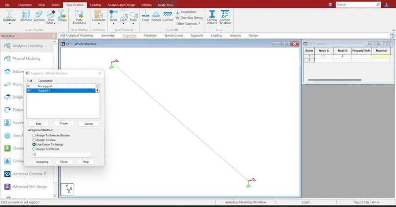
Supports are given to the respective nodes.
Specifications > Supports > select the supports > click enter
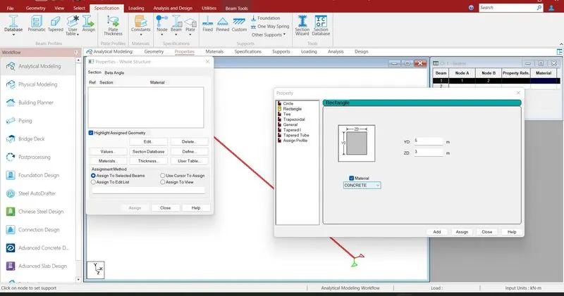
Assigning the properties to the beam .
Specification > Prismatic > Rectangle > enter dimensions > select the beam > assign the properties to selected beams.
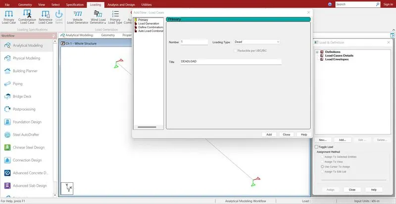
Defining the load cases .
Loading > Load case detail > select load > Add

Add > member load > enter the value > ok
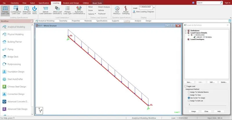
Select the defined load > select the beam > Assign to selected beam > click enter
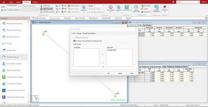
Run analysis > go to post processing mode > Results
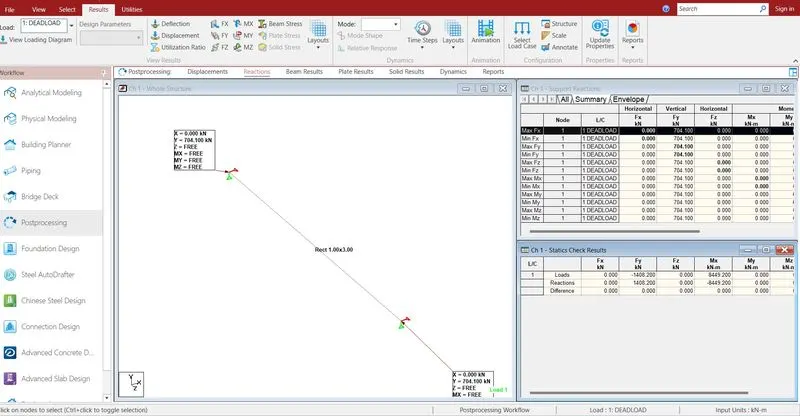
The reactions are generated at the end of the nodes .the reaction value is 704.1 KN
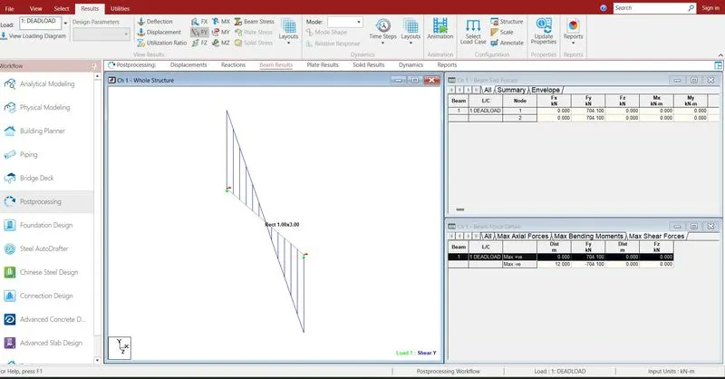
- The shear force is maximum at the end and minimum at the end of the mid span.
- Exactly at 6m the shear force is 0.
- At node 1 the shear force is positive and node 2 the shear force is negative of value 704.1 KN
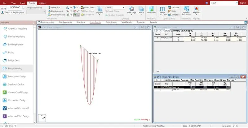
- The bending moment is maximum at midspan and minimum at the end support.
- The maximum bending moment is at the 6 m, the value is 2112.3 KNm
- The maximum displacement is 5.12mm occurs at the exactly mid span.
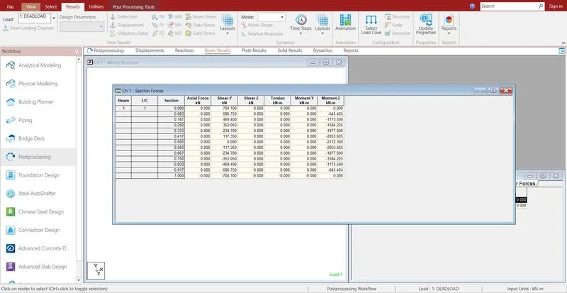
- Reports are taken printout which ever is necessary by using report option.
- In the report option we obtain the results of section forces, displacement, reactions, plate stresses.
- The exact report is to be taken further move to design process.