Week 4 Challenge
Aim : To calculate the earth pressure acting on the abutment wall .
Given data :
Backfill soil height – 7 m
Ground level - 3 m
Theory :
Earth pressure : The horizontal thrust exerted by the retained earth on a vertical structural element like wall, pier, abutment.
- Earth pressure at rest : When the vertical structural member is rigid and unyielding the soil mass is in a state of rest ( no displacement and deformations)
- Active Earth pressure (Ka ) : When the vertical structural member moves away from the backfill, the soil mass expands and there is no decrease in pressure.
- Passive Earth pressure (Kp ) : When the vertical structural member moves towards the backfill, the soil mass compressed.
Calculation : Ka = 0.35 ɣsat = 19 KN/m3 ɣw = 10 KN/m3 h = 3m
K1 = Ka . ( ɣsat - ɣw ) . h
= 0.35 . (19 - 10) . 3
K1 = 9.45 KN/m2
K2 = Ka . ( ɣsat - ɣw ) . h
= 0.5 . ( 19 – 10 ) . 7
K2 = 31.25 KN/m2
Aim : To prepare the model in a STAAD Pro and perform the analysis and justify with the results.
Theory : The general steps to be create a STAAD Pro model is given below,
Step 1 : Create the nodes by using the nodes cursor.
Step 2 : Joining the nodes by using the respective beam plate cursor.
Step 3 : Supports given to the nodes whether its pinned or fixed or any other custom supports
Step 4 : specifications given to the respective beams plates
Step 5 : Assign the live load as per calculation
Step 6 : Save the model and perform the analysis
Step 7 : The results are obtained and discuss with the results
Step 8: Take the print out of report of necessary results.
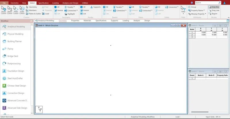
Creating the nodes by using node cursor.
Open the STAAD Pro window > Select > Node cursor > enter the value with respect to X Y Z axis > click enter.
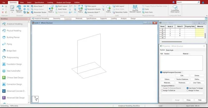
Join the nodes by using plate cursor.
Select > plate cursor > join by dragging the mouse or enter the node numbers > click enter
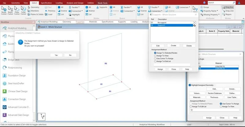
Supports are given to the respective nodes.
Specifications > Supports > select the supports > click enter
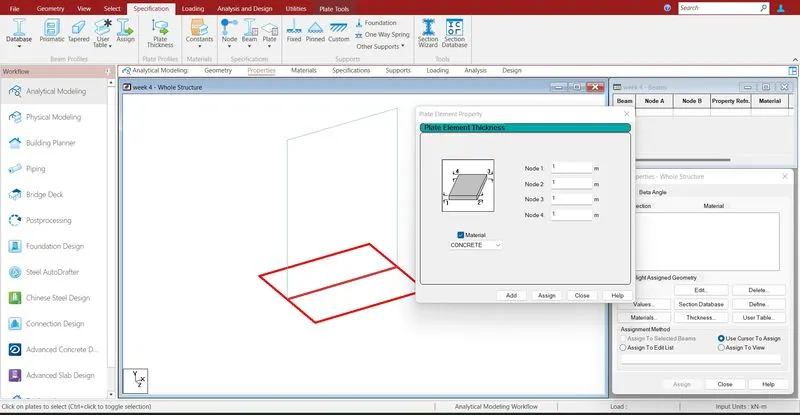
Assigning the properties to the plate .
Specification > Plate thickness > enter dimensions > select the plate > assign the properties to selected plates.
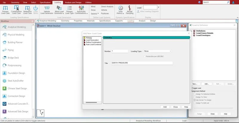
Defining the load cases .
Loading > load case details > earth pressure > Add
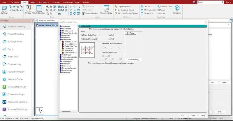
earthpressure > plate load > hydrostatic > give the value with respect to calculation > assign the load
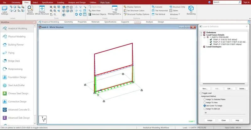
Assigned all the loads with respect to calculations and model has been prepared for run analysis
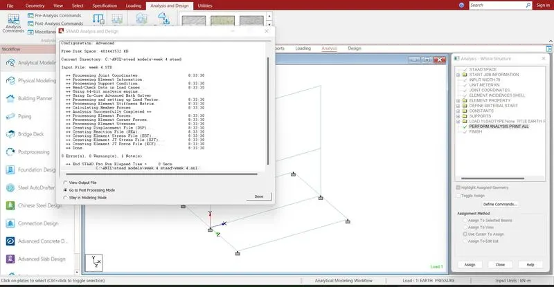
Run analysis > go to post processing mode > Results
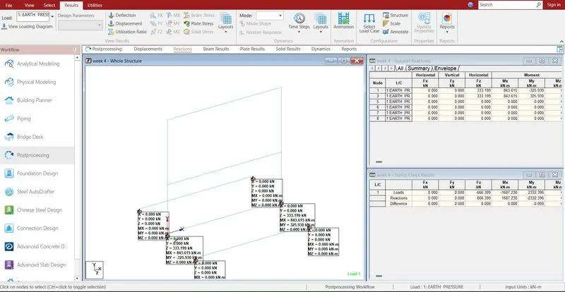
The reactions are generated at the end of the nodes .
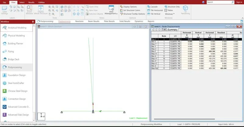
The deflection of the wall has been showned here.
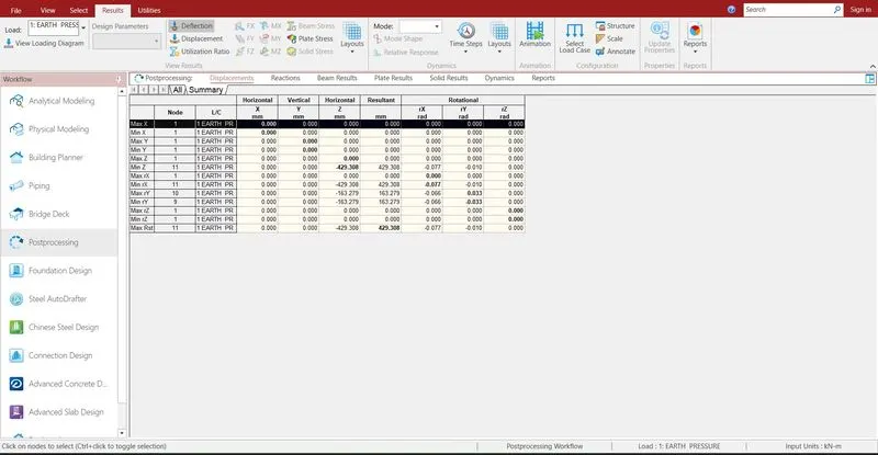
The maximum displacement value is 429.308 mm in Z direction.
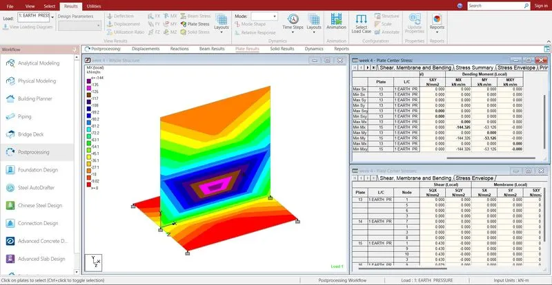
- The maximum bending moment in X direction is 144.326 KNm
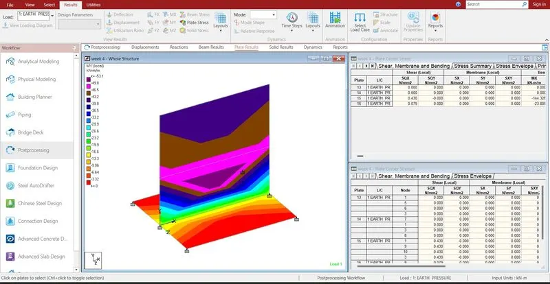
- The maximum bending moment in X direction is 53.126 KNm
- Reports are taken printout which ever is necessary by using report option.
- In the report option we obtain the results of section forces, displacement, reactions, plate stresses.
- The exact report is to be taken further move to design process.