Week 5 Challenge
Aim : To calculate the design wind load for the bridges to be designed at Mumbai .
Given data :
Height of the bridge above ground level – 9 m
It is located in open terrain .
Pier size – 1.5 x 1.5 m
It is scattered obstruction of height less than 10 m
Theory : The load or force on a structure arising from the impact of win don it.
The basic design wind speed is given by :
Vz = Vb k1 k2 k3 k4,
where Vz = design wind speed at any height z in m/s
k1 = probability factor (risk coefficient) (see 5.3.1)
k2 = terrain roughness and height factor (see 5.3.2)
k3 = topography factor (see 5.3.3)
k4 = importance factor for the cyclonic region (see 5.3.4).
The design wind pressure is given by :
P z = 0.6V2 z
where pz = wind pressure in N/m2 at height z,
Vz = design wind speed in m/s at height z.
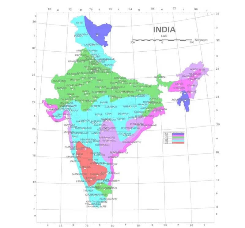
Calculation : K1 = 1.07 , K2 = 1, K3 = 1, K4 = 1.3, Vb = 44 m/s
Vz = 44 x1,07x1x1x1.3
Vz = 61.204 m/s
Wind pressure Pz = 0.6V2 z
Pz = 0.6x61.2042 = 36.72 KN/m2
Aim : To prepare the model in a STAAD Pro and perform the analysis and justify with the results.
Theory : The general steps to be create a STAAD Pro model is given below,
Step 1 : Create the nodes by using the nodes cursor.
Step 2 : Joining the nodes by using the respective beam plate cursor.
Step 3 : Supports given to the nodes whether its pinned or fixed or any other custom supports
Step 4 : specifications given to the respective beams plates
Step 5 : Assign the live load as per calculation
Step 6 : Save the model and perform the analysis
Step 7 : The results are obtained and discuss with the results
Step 8: Take the print out of report of necessary results.
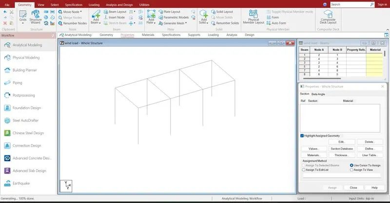
Creating the nodes and join the nodes by using node and beam cursor.
Open the STAAD Pro window > Select > Node cursor > enter the value with respect to X Y Z axis > click enter.
Select > beam cursor > join by dragging the mouse or enter the node numbers > click enter
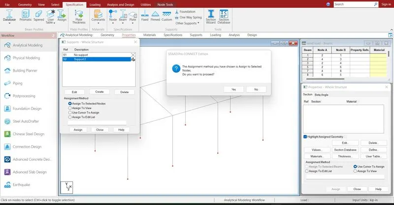
Supports are given to the respective nodes.
Specifications > Supports > select the supports > click enter
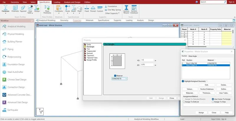
Definingining properties to the beam .
Specification > Prismatic > Rectangle > enter dimensions > add >
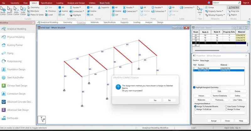
Assigning the properties to the pier and beam .
double click on propertie > select the beam > assign the properties to selected beams.
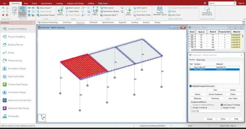
Creating mesh like plate size of 0.5 m to make a deck slab
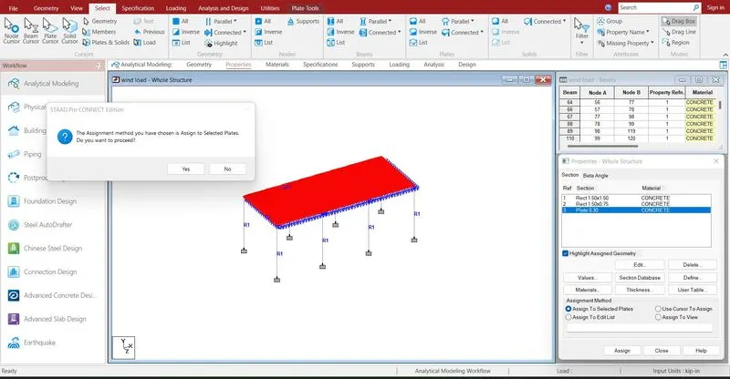
Assigning properties to the plate of thickness 0.3 m.
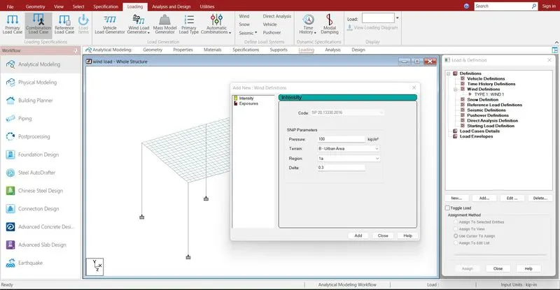
Defining the load cases .
Loading > definition > wind load > Add > double click on load > select sp 20 2016 > enter the pressure > add
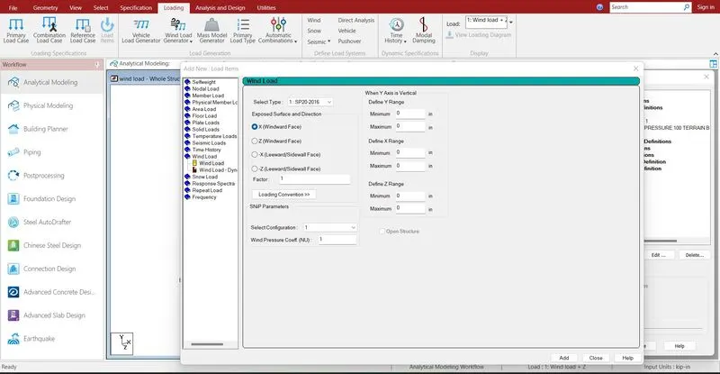
Load case > Add > wind load > add > give the direction > enter the range value > ok.
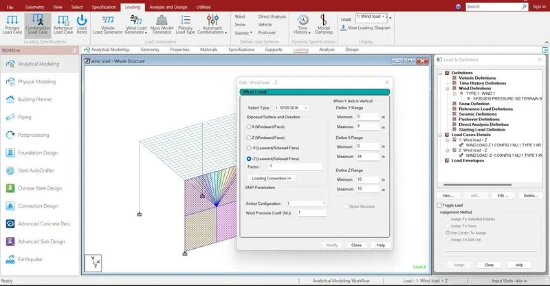
loads are assigned to the model with respect to direction.
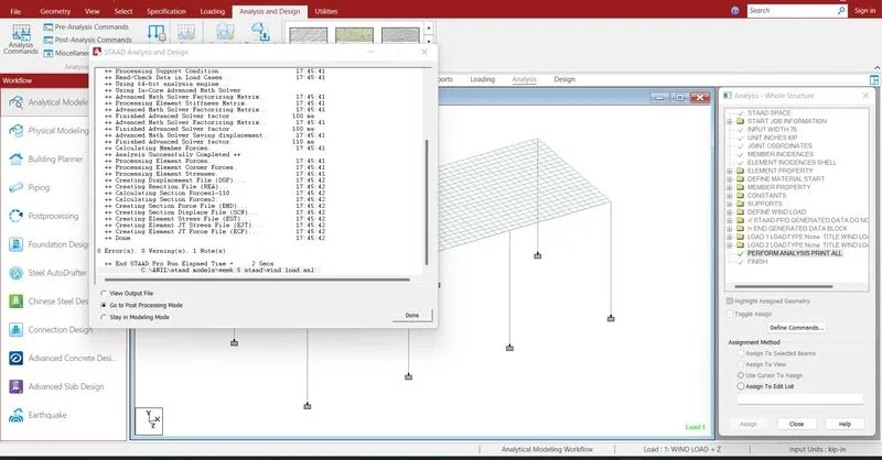
Run analysis > go to post processing mode > Results
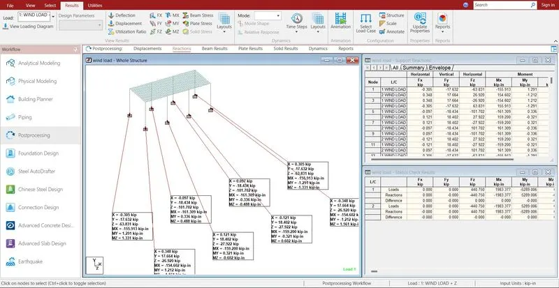
The reactions are generated at the end of the nodes .
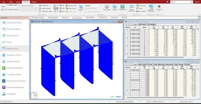
- The shear force maximum in x direction 19.964kn on 62 beam.
- The shear force minimum in x direction -18.434kn on 8 beam.
- The shear force maximum in y direction 16.376kn on 42 beam.
- The shear force minimum in y direction -16.376kn on 44 beam.
- The shear force maximum in z direction 28.244kn on 8 beam.
- The shear force minimum in z direction --28.244kn on 9 beam.
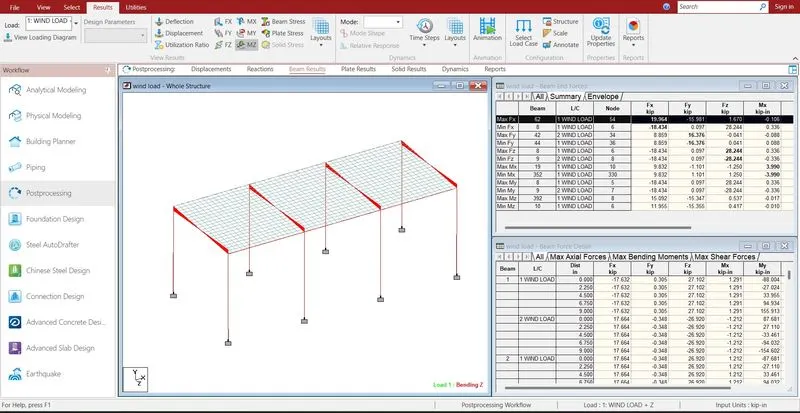
- The bending moment maximum in x direction 3.99knm on 19 beam.
- The bending moment minimum in x direction -3.99kn on 352 beam.
- The bending moment maximum in y direction 161.309kn on 8 beam.
- The bending moment minimum in y direction -161.309kn on 9 beam.
- The bending moment maximum in z direction 83.784kn on 8 beam.
- The bending moment minimum in z direction -84.390kn on 6 beam.
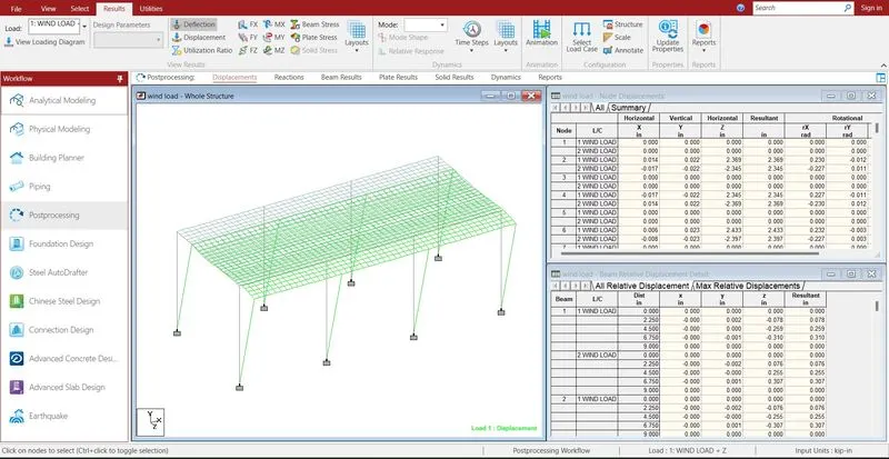
The max displacement is occur in z direction is 2.44 on517 node and -2.14 on 537 node
- Reports are taken printout which ever is necessary by using report option.
- In the report option we obtain the results of section forces, displacement, reactions, plate stresses.
- The exact report is to be taken further move to design process.