Week 8 - Challenge 5 - Door Trim Lower
DESIGN OF DOOR TRIM LOWER USING CATIA
AIM: To design a door trim lower component of an automobile using class A surface obtained using catia software
Design process:
- Creation of tooling axis
- Draft analysis
- Generation of class B surface
- Generation of class c surface
- Solid body of door trim lower
Commands used:
- Boundary
- offset surface
- Multi extract
- Extrapolate
- Split
- Trim
- Sweep
- Multi section surface
- Join
- spline
Class A surface:
Class a surface is an asthetic surface which is visible to the customer
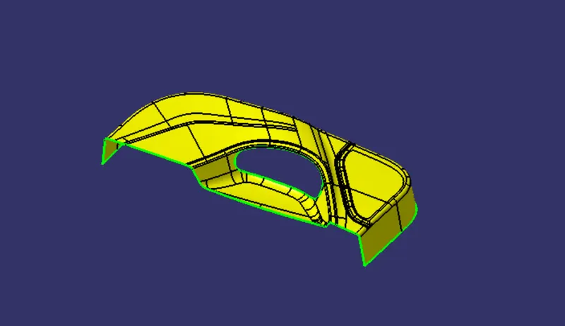
Creating a tooling axis:
The methods employed for creating the TOOLING AXIS is
- Normal to surface
- point - direction
- Bisection method
While creating a tooling axis of the door trim lower we generally take use of point direction method , take a flat surface for creating the line which will clear the draft analysis of our class A surface
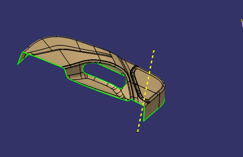
So here the yellow colored line represents my tooling axis and while performing the draft analysis we can able to find whether our tooling axis able to clear the draft on all my surfaces ,that's the way we can find the better positin for the toolling axis
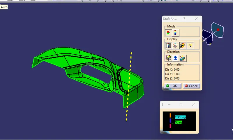
So , here my tooling axis cleared the draft analysis. Now proceed to the Class B surface creation
Class B creation:
The surface which lies beneath the class A to a small offsetted distance and often it is called as an engineering surface where the components like doghouse,heat stakes, ribs, screwbosses lies
First of all check the outerlying boundary of the class A surface ang get to conclude whether there may be a possibility of an open patches the try to offset the class A surface to 2.5 mm
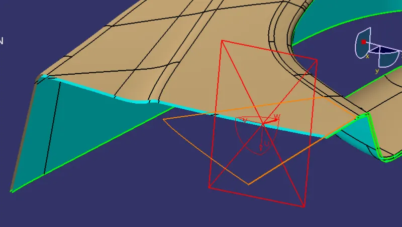
So the top surface is the class A surface where the blue bottom surface is my offsetted surface to 2.5mm
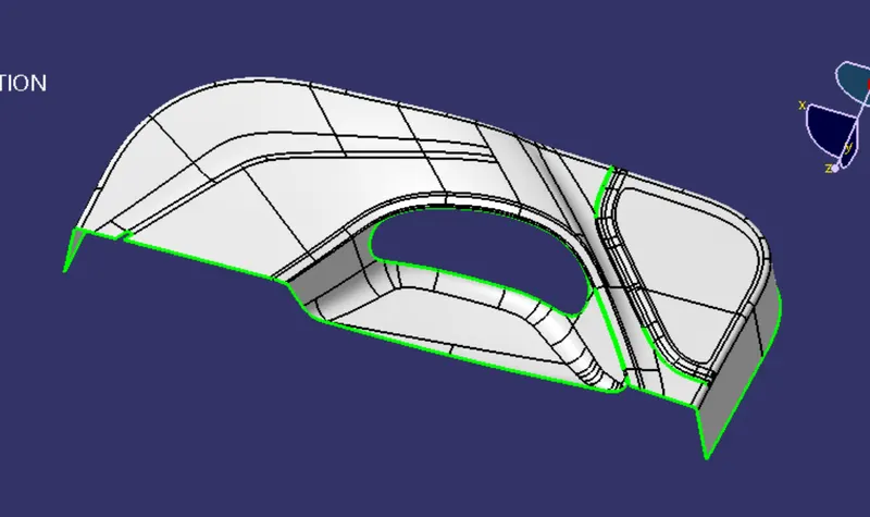
from the offsetted surface we clear observe some patches potraiting in green color irresepective of the boundary so e need to employ some method to counter them
Now employ the best method for creating the class B surface Here I created the class B surface by assuming the class A into 4 intersections
- holder patch 01
- Top patch 02
- corner surface03
- Side walls04
Now use the mutiple extract command to extract the 4 assumed surfaces of the Class A by excluding the fillets as they might creeate some problems so the can be compensated at end
After extracting all the surfaces, extrapolate the boundaries to an extent with respect to other surface boundaries
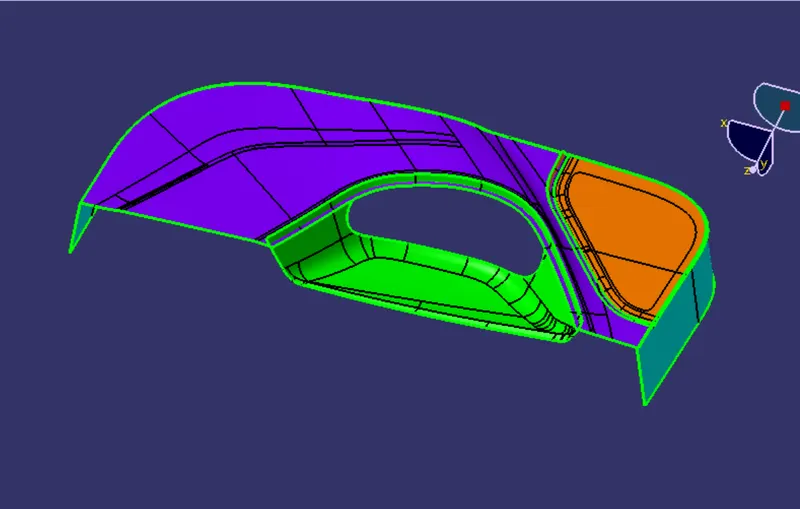
these are the 4 extracted surfaces which are extrapolated to an extend to the respective boundary then trim the surfaces so, from the product of the trim we can able to clear the patches obtained in the offsetted surface
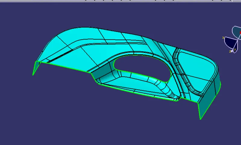
Then apply the fillets to the final trimmed surface
now the final B surface is
Creation of class c surface :
genearlly class c surface is the surface that lies as an intermediate joining between class A and class B surface Generally class C is grnerated by using class A surface
For this the class A is subdivided into two surfaes oneis the entire body and other one is the patch at the holder So rather then sweeping the entire surface better to do it by surface to surface so that there might be no problem at the final trim or final joining operation

So with respect to the draft direction provide a draft of 3 degree and with respect to the reference surface provide 90 degrees or a draft of 3 degree to the 90 degrees value .So at the bottom of the side walls the surface can be easily cleared in the moulding process so no draft is allowed fot it . At the patch hole no draft is necessary
Final component:
Now after craeting the class B and class c surfaces then Use the join command to join the Class A and class c surfaces
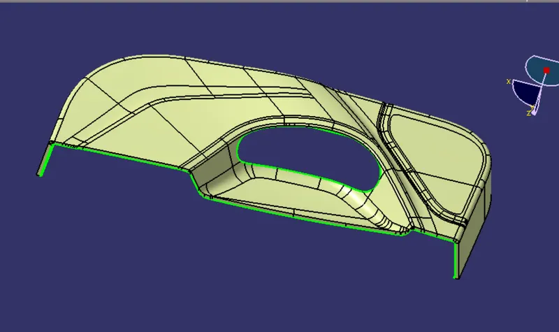
then Trim it with the Class B surface During trimming ckeck whether proper intersection is possible betwwen class A ans C combined and class B surface for making the trim operation smooth , if else try to extrapolate the particular surface where the intersection is not happening properly , then the component is obtained
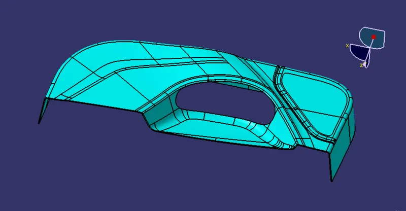
Now do the draft analysis for the component check wherther it is claering all the surfaces draft or not then proceed or else make the surface modification to clear the problem
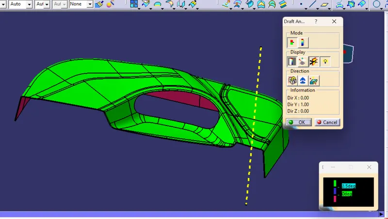
some surfaces on the class c cant be able to clear the draft because due to the class A surface Some modifiction need to be done on the class A to obtain better draft analysis on the complete body
After completing the draft analysis ues the solid surface feature to generate a solid body
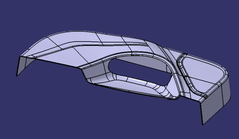
Conclusion:
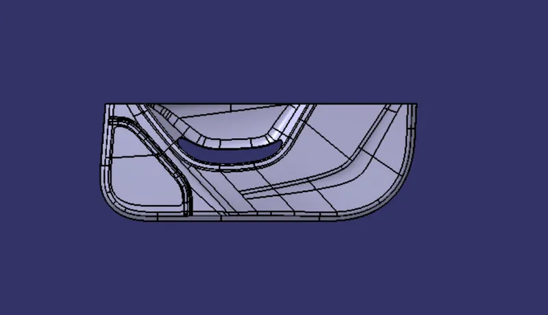
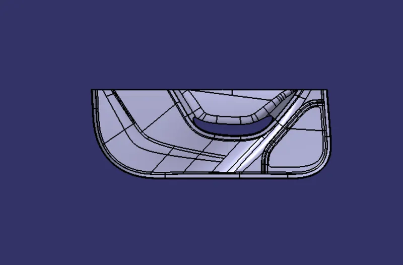
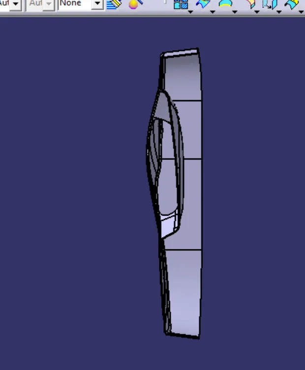
Thus the door trim lower component is created with the help of class a surface upon generating the Class B and class c surfaces and applying the proper draft analysis using catia software
the views are
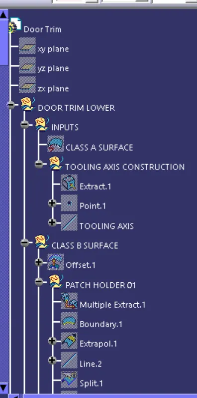
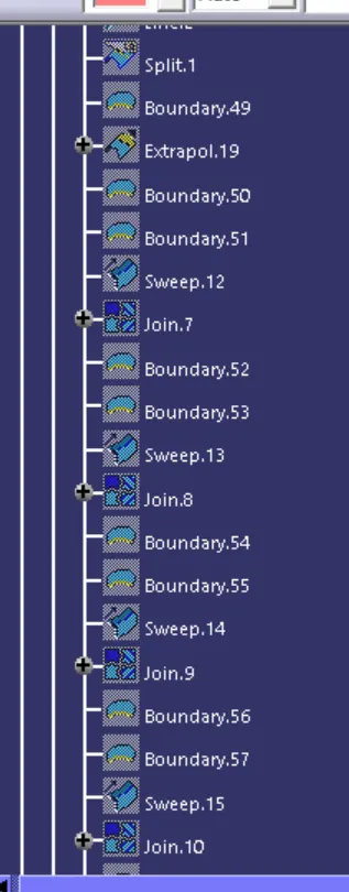
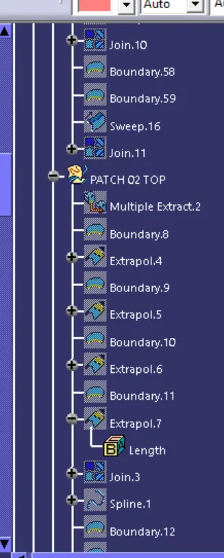
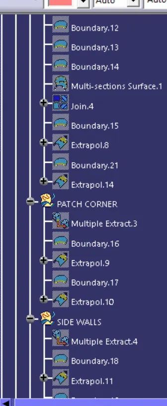
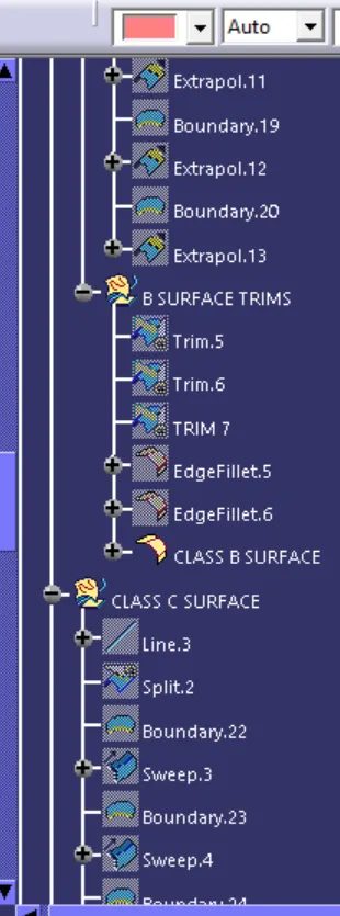
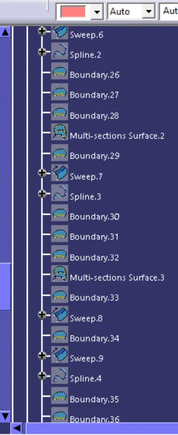
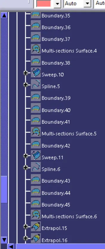
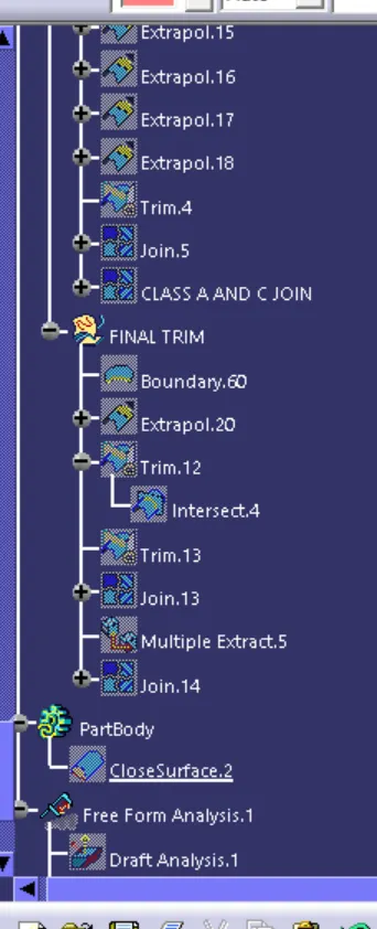
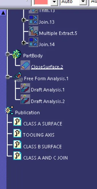
Tree structure: