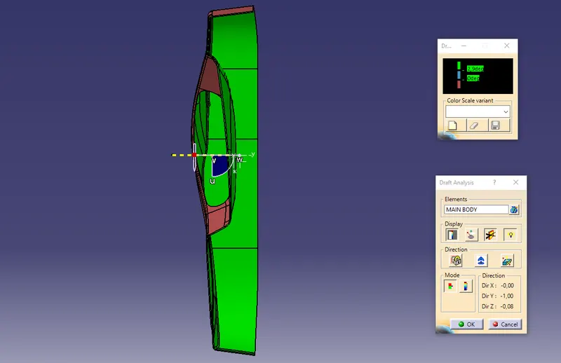
Week 8 - Challenge 5 - Door Trim Lower
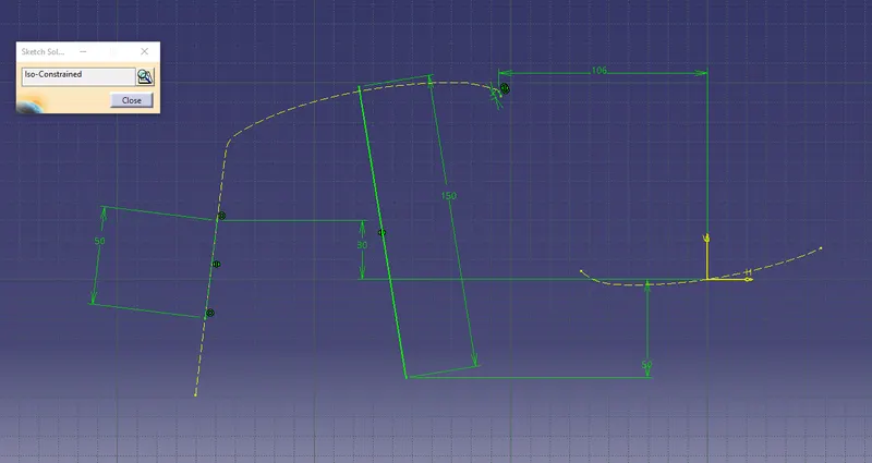
- First of all place an axis in the middle point of the door trim "planar" face. This axis sys allows to create two intersection (in two perpendicular planes), and thus two bisecting lines, respectively.
- Sketch 1: considering the critical walls of the first intersection, create a line tangent to each. Then the first bisecting line can be created.
- Skecth 2: considering the critical walls of the second intersection, create a line tangent to each. Then the first bisecting line can be created.
- The real tooling axis will be the resulting bisecting line between Sketch.1 and Sketch.2.
Skech 1
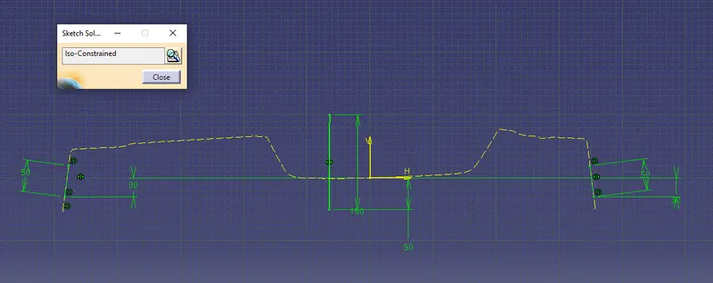
Sketch 2
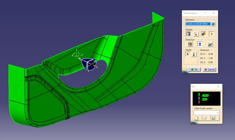
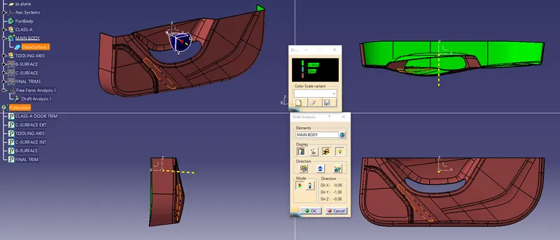
- The first attempt of Draft Analisys on Class-A surface with the use of the Tooling Axis can now be done.
- The result is completely green, meaning that the surface at this stage of design can be cleared along the selected tooling axis.
Preliminary Draft Analisys on Class-A using the Tooling Axis
- To discover which surfaces cannot offset by simply using the command, I start by offsetting the whole Class-A by 3mm.
Then I delete all the zones having a computational error and these become the part of B-Surface to re-design manually. - The parts which are better to re-design due to gaps creation during offset command are: Switch Bezel pocket, Speaker Area, Lower Flange.
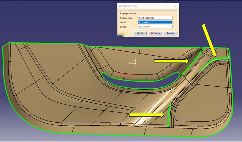
- Trim all the re-worked parts and offset by 2,5mm
- Apply again the missing edge-fillets on the B-Surface with the role: "Class-A-RAD" - "THK value" (for inward edges), or "A-RAD" + "THK value" (for outward edges).
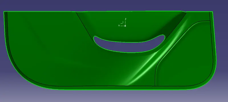
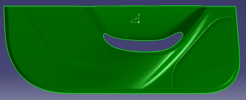
- To Create the C-Surface, Class-A boundaries have been used to generate a set of sweeps all around the part.
- Based on the orientation of the edge, use the tooling axis as reference. keep checking the resulting C-Surface Draft Analisys and, when it is strictly required, use instead Class-A as reference surface as an alternative method for sweep.
- This time it was necessary to operate almost edge by edge, because of complexity of the door trim shape. A combination of commands such as Extrapole, Trim and Multi-Section were used to reach "no gap" situation.
- Join A-B-C surfaces. This surface must have no selectable boundaries to be good.
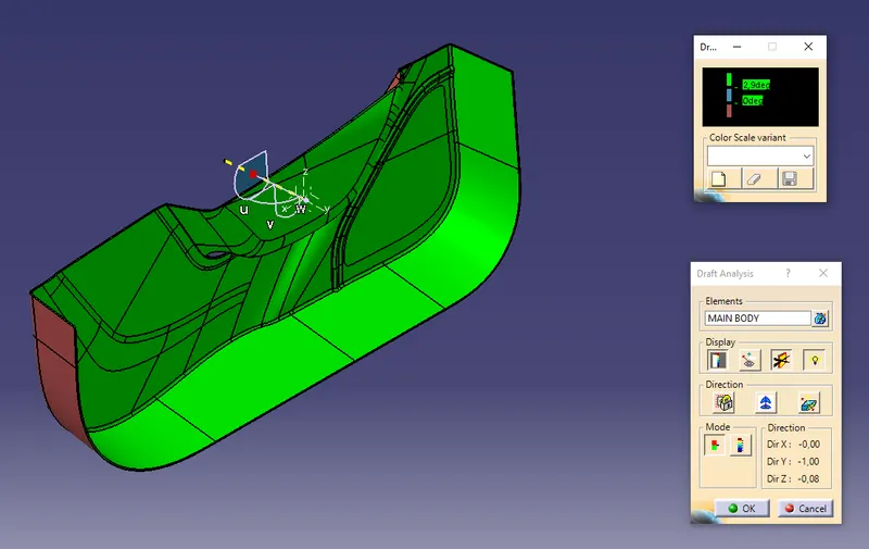
C-Surface(s)
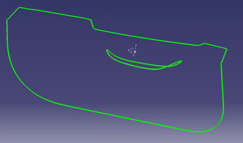
ISO VIEW
FRONT VIEW
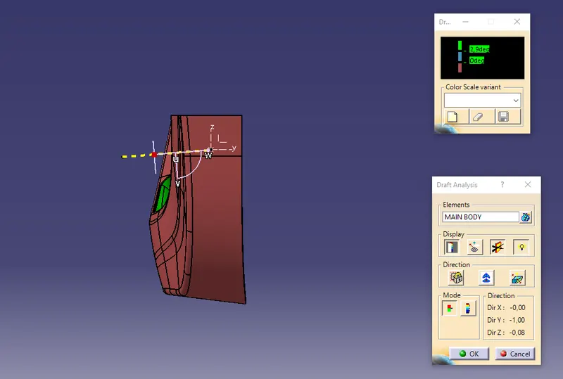
SIDE VIEW
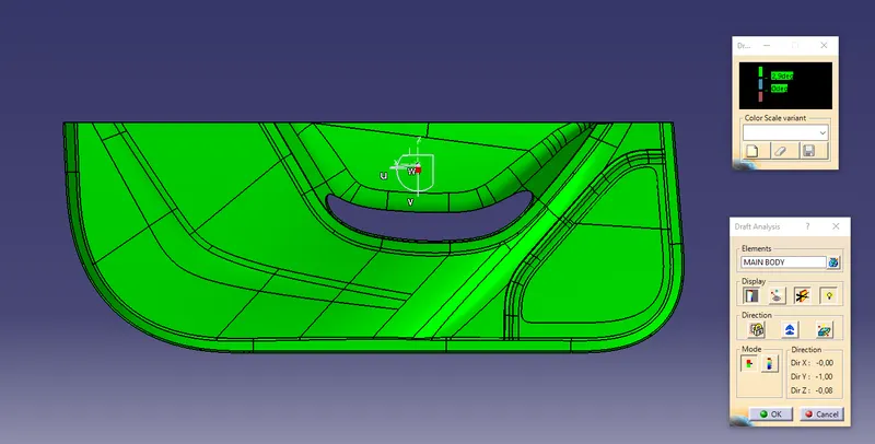
TOP VIEW