Week 8 - Challenge 4 - Bumper
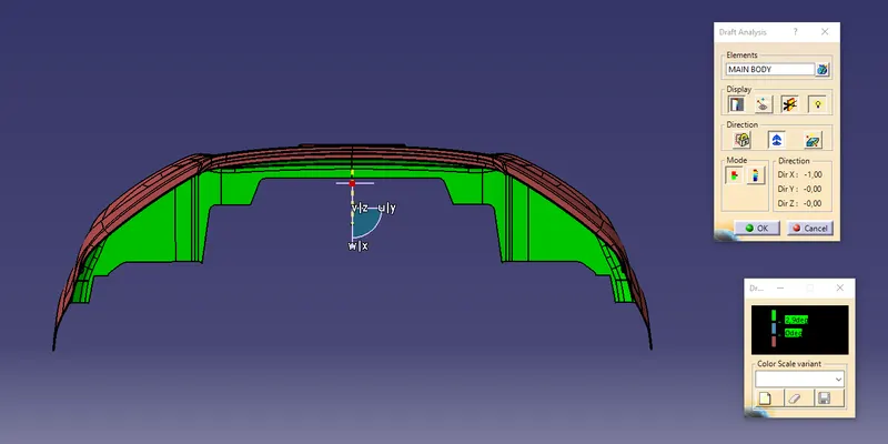
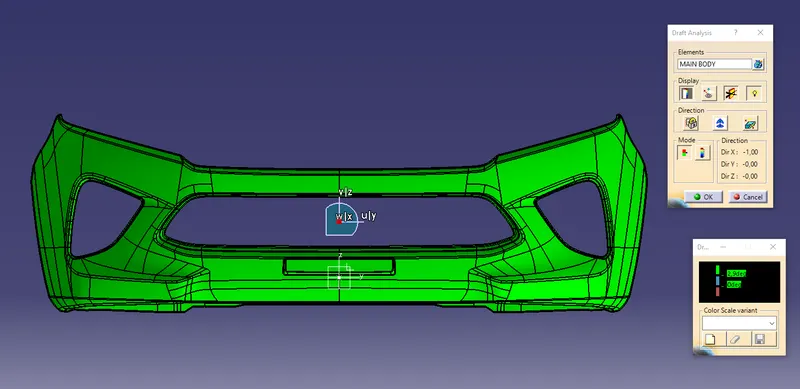
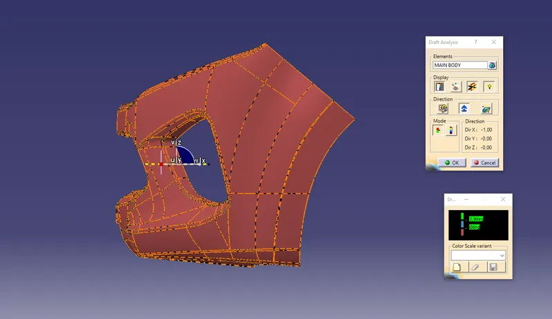
Preliminary Draft Analisys on Class-A surface
- Upon a trial and error analisys, it is clear that the tooling axis of this bumper is simply the X-axis.
- The result is completely green, meaning that the surface at this stage of design can be cleared along the selected tooling axis.
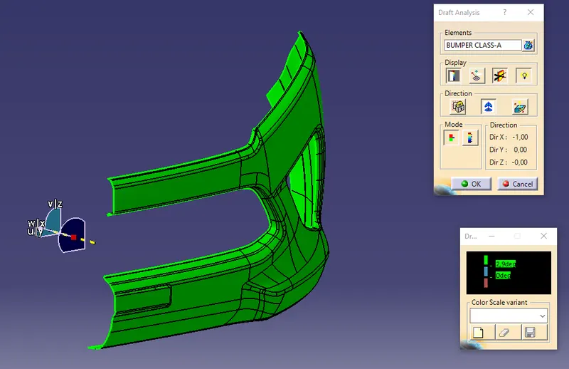
- To discover which surfaces cannot offset by simply using the command, I start by offsetting the whole Class-A by 3mm.
Then I delete all the zones having a computational error and these become the part of B-Surface to re-design manually. - The parts to re-design are: top flange, grid flange, licence plate area.
First Offset, before re-design
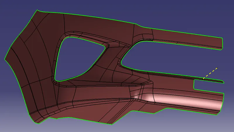
After re-design
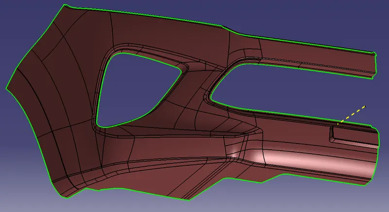
- Apply again the missing edge-fillets on the B-Surface with the role: "A-RAD" - "THK value" (for internal edges), or "A-RAD" + "THK value" (for external edges).
- To Create the C-Surface, Class-A boundaries have been used to generate a sweep with reference surface (Class-A itself), of 90°. This time it was necessary to operate almost edge by edge, because of complexity of the bumper shape. So each sweep was accurately extrapolated and trimmed until reaching "no gap everywhere".
- Join A-B-C surfaces. This surface must have no selectable boundaries.
Edge Fillets
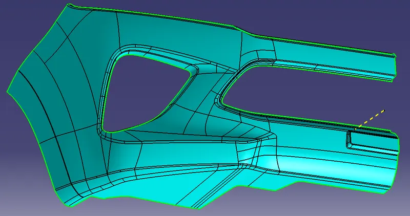
C-Surface(s)
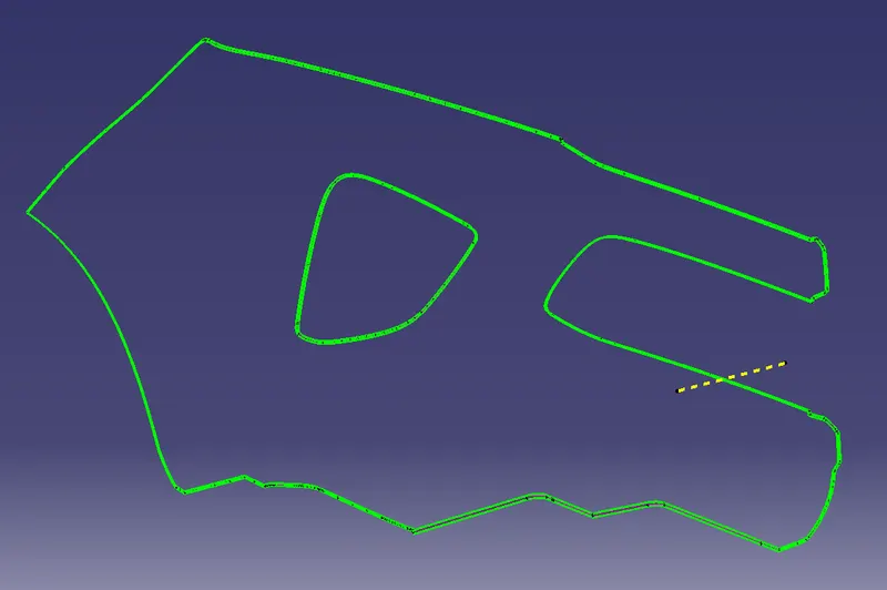
Final Trim
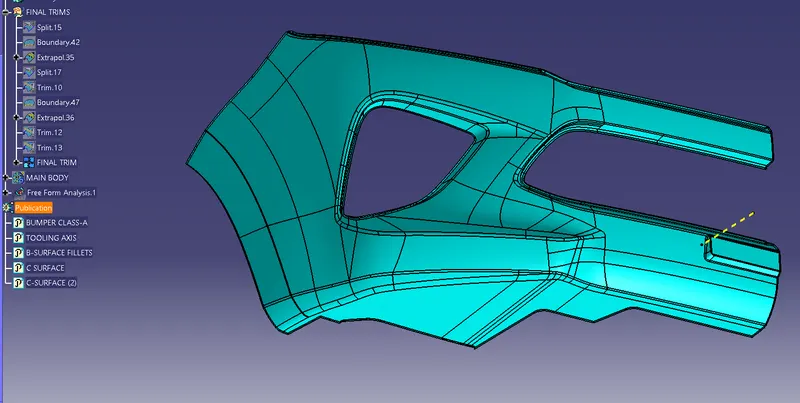
- Use Close Body feature inside a PartBody. At the end I mirrored the part to make the entire bumper visibile.
- The final Draft Analisys should show that both, Class-A, B and C surfaces can be cleared along tooling axis.
ISO VIEW
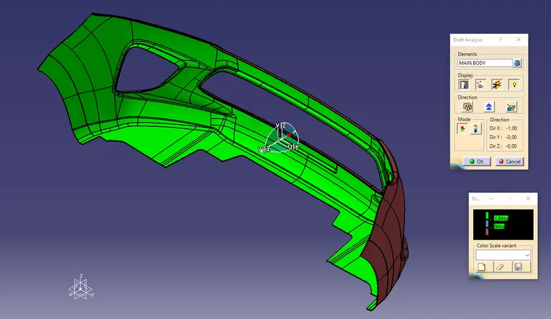
FRONT VIEW
SIDE VIEW
TOP VIEW