Week 8 - Challenge 5 - Door Trim Lower
DOOR TRIM LOWER DESIGN
OBJECTIVE:
To create the Door Trim Lower Plastic component through the given Class-A surface. To begin with, the tooling axis for the given Class-A Surface should be created meeting the requirements of the draft angle and at the end perform the Draft analysis on the model.
TOOL USED: CATIA V5
GIVEN:
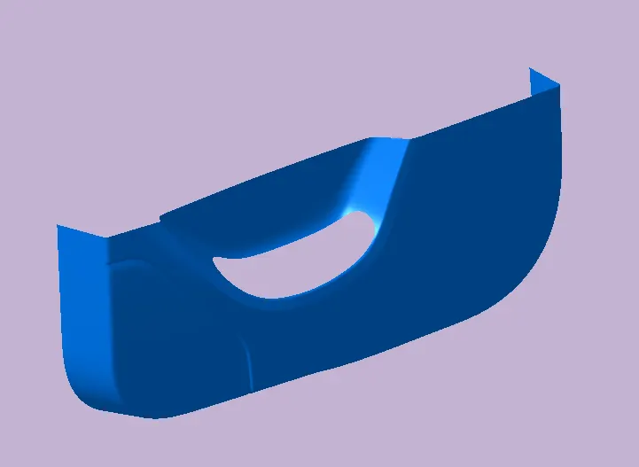
Thus the following Class-A surface as the inuput and the thickness of the plastic component is 2.5 mm.
STAGE_1: CREATING TOOLING AXIS
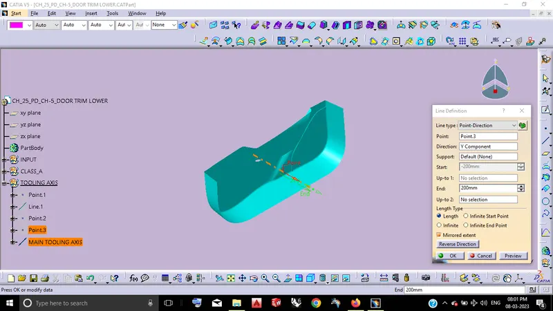
Tooling direction is main consideration for plastic part and the mold parts because it defines the movement of the mold part and possibility of plastic part come out from the mold part. And it also helps to define the two halves of the plastic componet like core and cavity parts. Consider this Classs-A along with Y-direction has become its tooling direction and following are,
By using of Point-Direction along with YComponent Line Definition.
STAGE_2: DRAFT ANALYSIS FOR CALSS-A
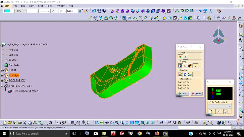
By using the Feature Draft Analysis by the defined Main tooling Axis thus the following results are,
Consider the minimum Draft angle of the Plastic component will becomes 3 deg on itself.
STAGE_2: SURFACE MODELING
STEP_1: CLASS-B CREATION
Class-B surface, In which can be easily defined as the thickness of the part and it is not visible which is inside surface of Class-A. Let us Consider the input thus the thickness of the plastic component will becomes 2.5 mm on itself and the Class-B surface definied by the followings are,
By using of Offset Surface Definition.
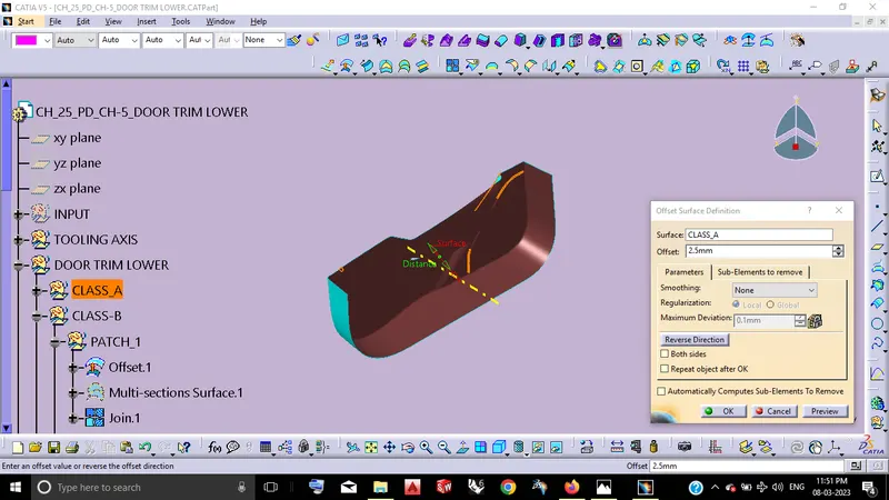
From the above offset of 2.5 mm of thickness of the plastic component we obtain its B-side of its surfaces but it having some of the missed patches on itself while offsetting. So we can obtain the fine surface of Class-B by solving this following patches one by one and the solvings are,
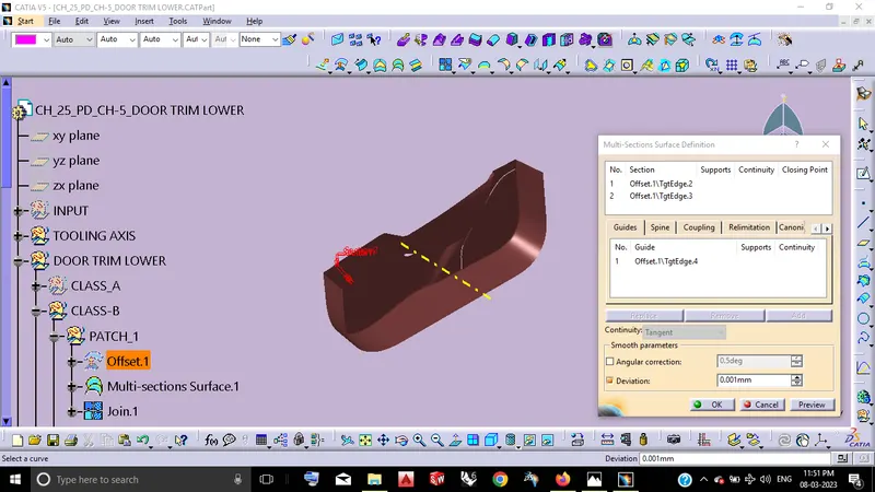
By using of Multi-Section Surface definition thus the Patch-1 becomes closed.
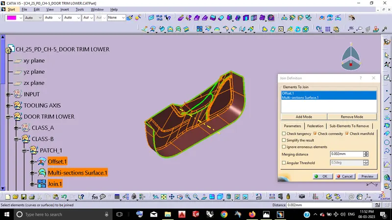
By using of Join definition.
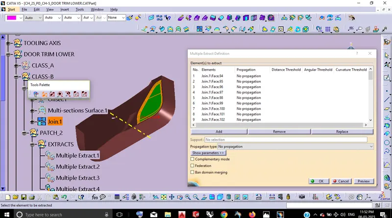
By using of Multiple Extract definition.
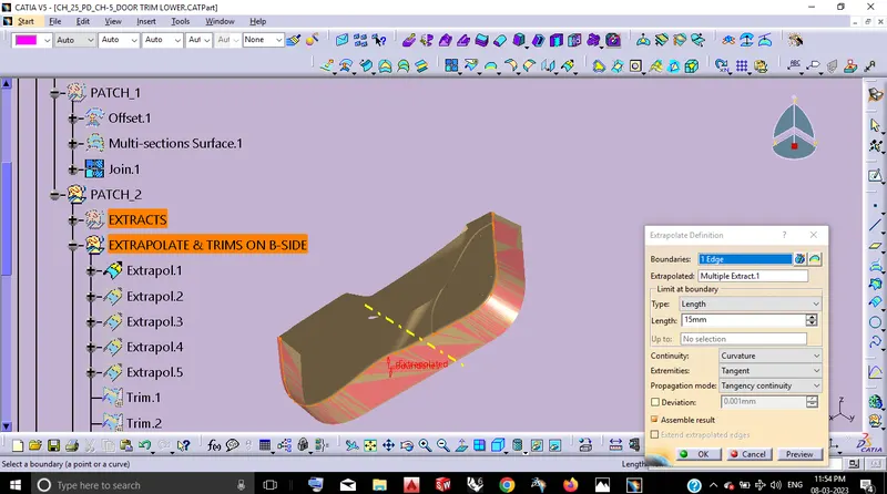
By using of Extrapolate Definition by creating boundaries with in the limits where we need to get extrapolated.
By using of Trim Definition.
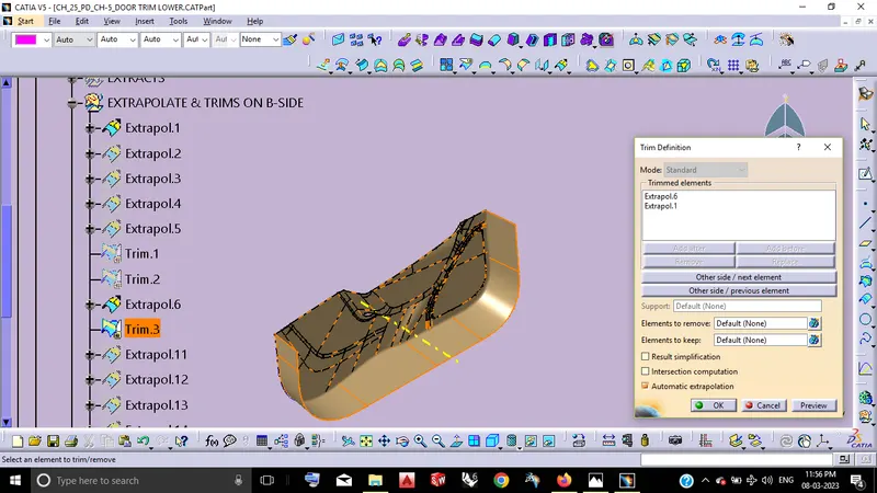
By using of Edge fillet Definition. Along with this Edges has maesured and it becomes less than 0.5 mm of radius on itself. Let us consider this two edges become followed thus the minimum radius of 0.5 mm.
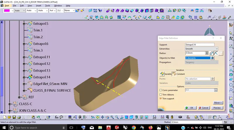
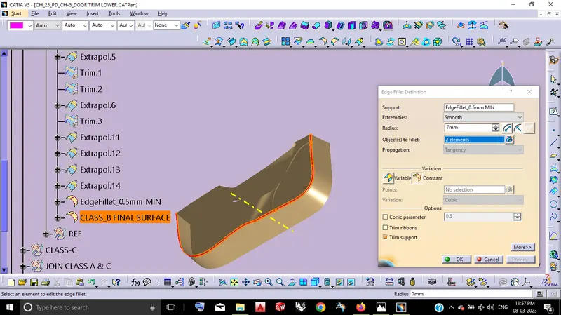
By defining this area radius should be checked from the above offseted one along with this by creating a 3 point circle then we can measure the radius of that particular edge should be defined. Then By using the Edge Fillet Definition with the apropriate measured dimension(R7mm). Finally here we arresting all the patches thus the Class-B final surface obtained.
STEP_2: CLASS-C SURFACE CREATION
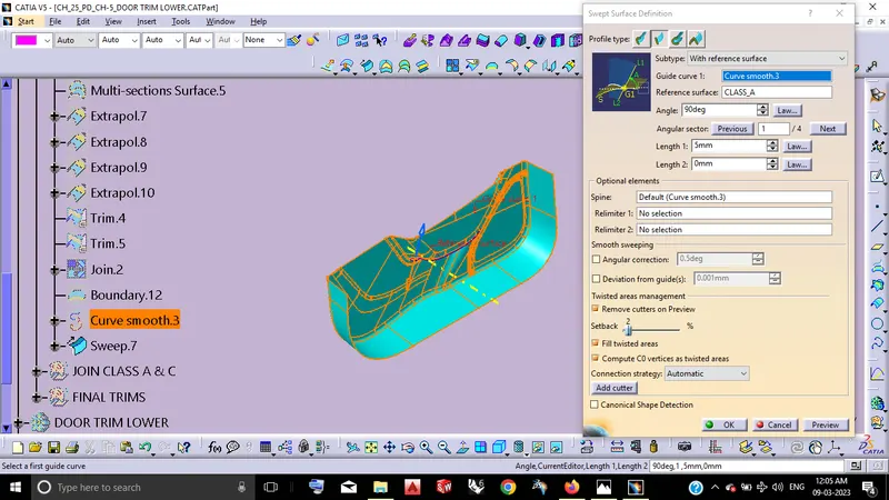
From the Class-A surface and along with the Tooling Direction by this two things helps to create Class-C surface this Plastic component and the followings are C-surface creation,
By using the Swept surface definition along with the the tooling direction and with ref surface feature thus the C-surface will obtained.
STEP_3: JOIN CLASS-A & C
Here considering Class-A & C surfaces we have small patch edge on the Class-A surface so that it becomes solved by the following then we obtain Class-A & C join surface.
By using of Extrapolate definition.
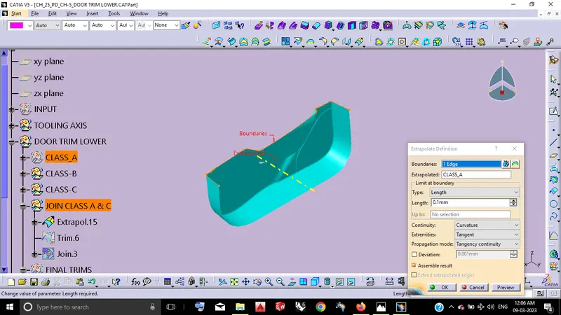
By using of Trim Definition.
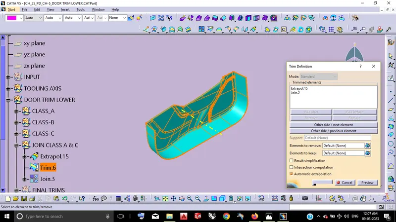
By using of Join definition.
STEP_4: FINAL TRIMS
Consider this thus the above Class- A & C joined surface and the Class- B surface trimed both of itself then finally we obtain the fully closed surface part body of the Door Trim Lower.
By using of Trim Definition.
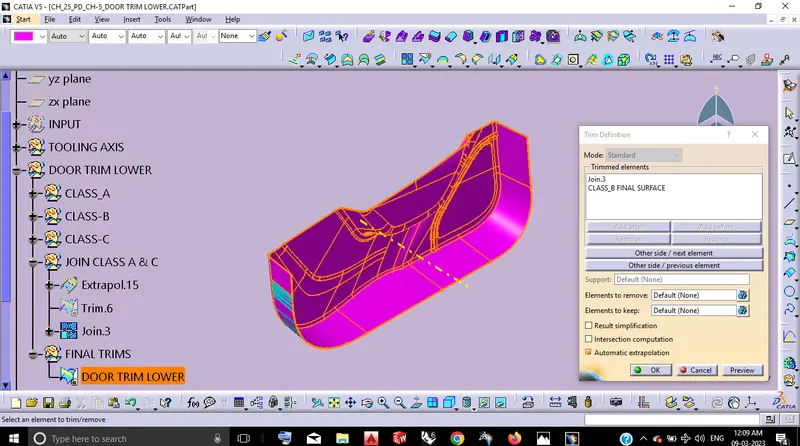
STAGE_3: CLOSE SURFACE DEFINITION
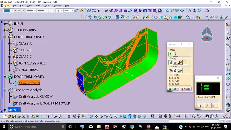
By using of CloseSurface Definition by the above closed surface that final trimed part which will becomes get solid part body.
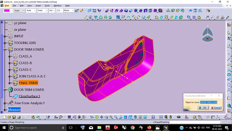
STAGE_4: DRAFT ANALYSIS FOR FINAL PART BODY OF DOOR TRIM LOWER
From the following this Draft Analysis with the min.Draft angle of 3Deg,
By using of Feature Draft Analysis.
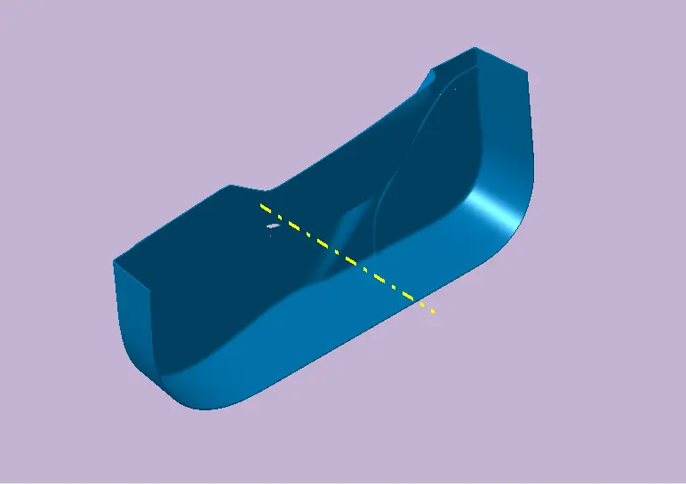
VIEW ORIENTATIONS:
ISO VIEW
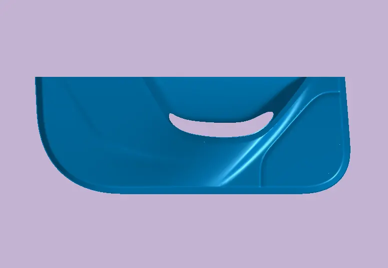
FRONT VIEW
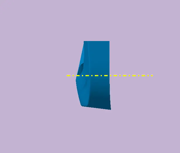
SIDE VIEW
TREE STRUCTURE:
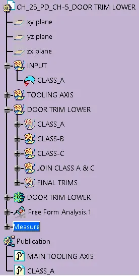
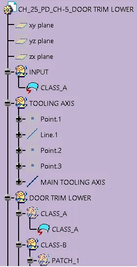
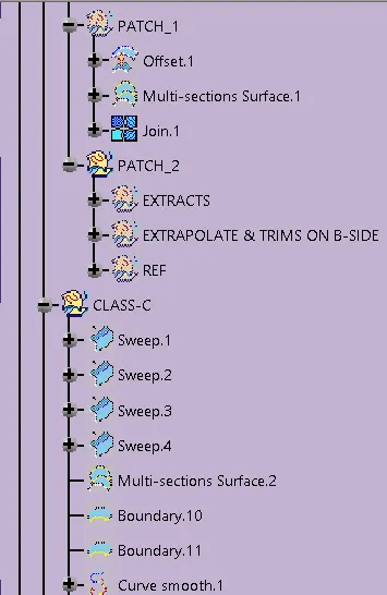
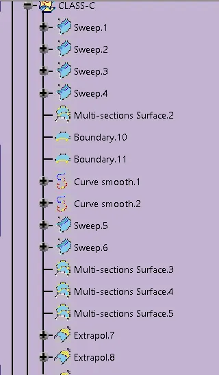
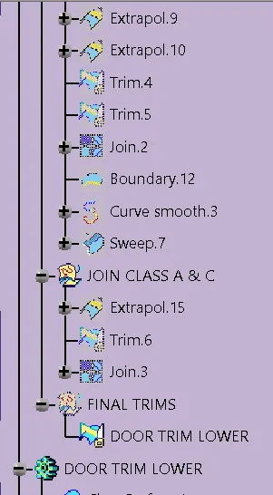
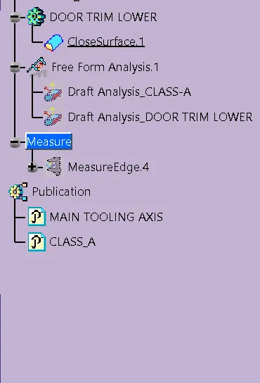
CONCLUSION:
Thus the Door Trim Lower Plastic component through the given Class-A surface to be done by using CATIA V5.
Tooling axis for the given Class-A Surface to be created.
Surface CATPart model to be done with the thickness of 2.5mm also the Solid part body of Door Trim by using Close surface. And
The Draft analysis on both the Class-A & Final Component model to be completed.