Week 8 - Challenge 5 - Door Trim Lower
OBJECTIVE
To create the Door Trim Lower's Plastic Component using the Class A Surface that is provided. Desired Thickness of the Plastic Component is 2.5mm with 2.9 degrees as the Draft Angle.
First, we have to create the required Tooling-Axis for the given Class A Surface while meeting the requirements of the necessary Draft Angle & then perform the Draft-Analysis Operation on the Class A Surface itself.
After that, we have to create the required Class B & Class C Surfaces using which we have to make the Final Plastic Component and perform Draft Analysis on it as well.
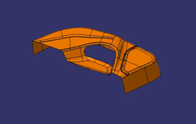
Class A Surface:
Class A is an aesthetic surface with the highest quality finish. Most Class A Surfaces for an Automotive Component are made using 'Autodesk-Alias' based on the final Concept-Sketch. All Class A surfaces should have 'Curvature-Continuity', meaning the continuity between the surfaces should share the same boundary. It is taken as a reference by the Automotive Plastic Designer to create 'Class B' and 'Class C' Surfaces.
 .
.
TOOLING DIRECTION:
The Tooling Direction is the direction that the mold pulls apart. The mold is built in two separate pieces,
- A Cavity side and
- The Core side.
The Core pulls apart from the Cavity and that's the Dyeline or the Tooling Direction. The direction in which the mold or core and cavity open is the tooling axis.
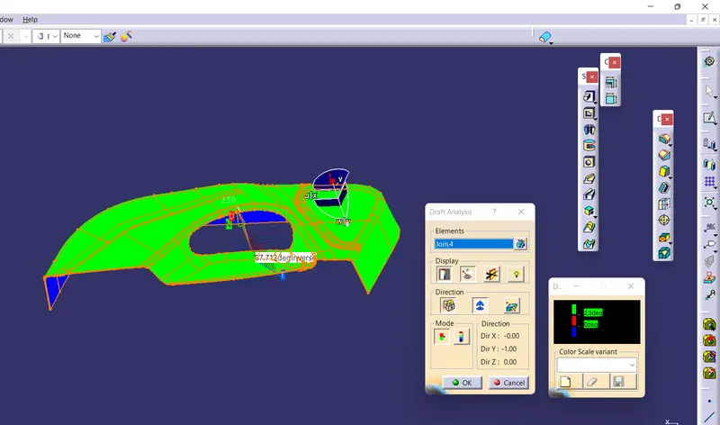
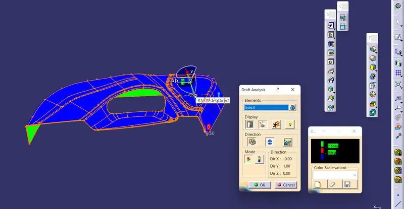
DRAFT ANALYSIS FOR THE CLASS A SURFACE USING THE MAIN TOOLING AXIS:
Before starting with a Draft Analysis Operation, we will go to the 'Customize View Parameters' option under the 'View Toolbar'. Then we will enter the 'Customize View Mode' where we will go under the 'Mesh' option and select 'Material' and press 'OK'.
To start the Draft Analysis in the Generative Surface Design Workbench, we will go to Insert and then look for the option called Analysis. Once found, we will go under that and click on 'Feature Draft Analysis. This will open the 'Draft Analysis' Dialogue box. There, we will ensure that under 'Mode' we have selected 'Quick Analysis', under 'Display' we will select Show or Hide the Colour I Scale and then select '3 Degrees' as the permissible draft angle. Then, under 'Direction' we will choose the icon with the symbol of the compass on it which stands for 'Use the Compass to define the new current draft direction'.
CONSTRUCTION OF THE CLASS B SURFACE:
We'll start the procedure by creating an offset for the entire Class A Surface at a distance of 2.5mm as that is the desired thickness for our final plastic component.
As this is a complex surface hence the offset will fail to offset every element according to our necessity. It'll select some sub-elements that belong to the filleted regions by themselves that we have to remove to get the rest of the surface that is offset.
These 'Sub-Elements' will get selected by themselves to be removed if we want to obtain the rest of the offset surface.
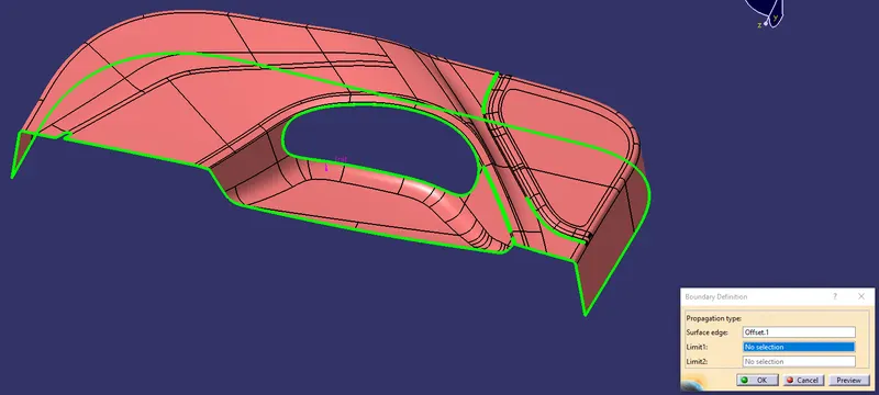
In the above image, CATIA is showing us the filleted regions where these sub-elements are located that are going to be removed after the offset operation.
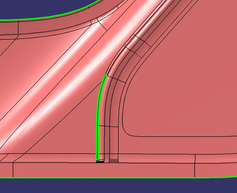
To fix all these Patches, we will use the JOIN command in which uncheck the CHECK CONNEXIVITY and in SUB-ELEMENTS TO REMOVE option we will select the filleted surface to remove and click OK. We will do the same for all PATCHES REGION.
After removing the filleted surface, we will disassemble the surface body by using the DISASSEMBLE command. Once the 2 surface domain created we will create the BOUNDARY curve for both surfaces.
After creating the boundary curves, we will use EXTRAPOLATE command to extend the surfaces till the intersection then we will use the TRIM command to remove the extra surfaces and they will be joined together automatically.
The same procedure is followed for all REGION PATCHES, and the final result is below with no PATCH REGION.
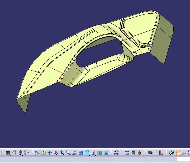
PROCEDURE TO CREATE THE CLASS C SURFACE:
We'll create the Class C Surface with respect to the Class A Surface and provide draft angles to those surfaces that are parallel to the Main Tooling Axis. Surfaces at the bottom won't be needing any draft angle as they'll get cleared by the core itself. To create the Class C Surface we have to use various commands such as Sweep with Reference Surface and With Draft-Direction depending upon the necessity and at places where it'll be difficult for us to create a surface using Sweep, we'll use Multi-Sections Surface to create those surfaces.
Now, we're going to Join the Class A Surface with both inner and outer Class C Surfaces as shown below:
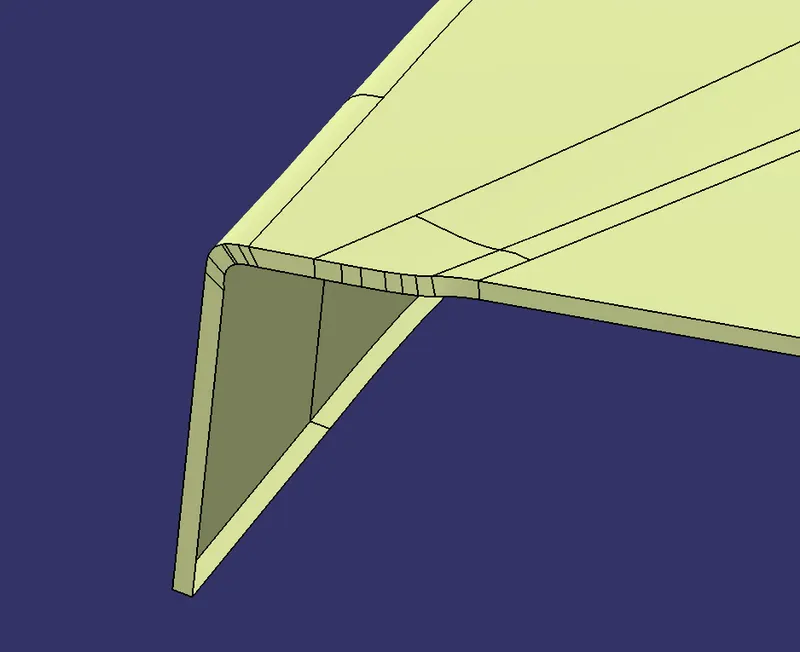
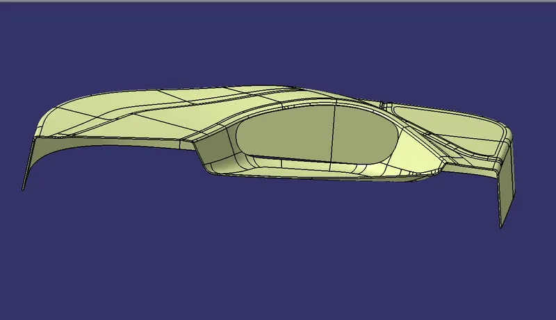
After that, we've to trim these joined surfaces with the Class B Surface but before that, we'll create an intersection between these two surfaces and see whether they're feasible to be trimmed with one another. We'll extrapolate those regions where they aren't intersecting and use the intersection command again to inspect whether the intersection is successful or not. When we'll obtain a complete intersection between these two surfaces we'll trim them together to obtain the final closed body as shown below:
FINAL SURFACE BODY:
FINAL SOLID BODY:
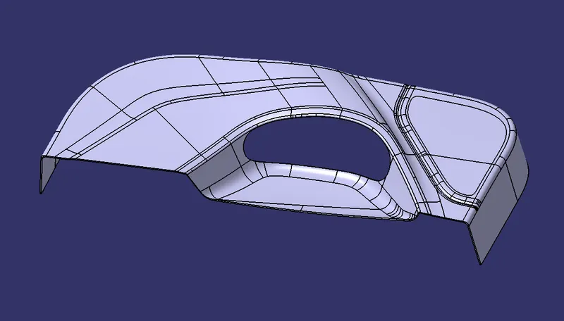
TREE STRUCTURE:
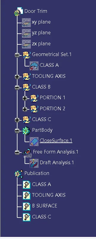
ISOMETRIC VIEW:
FRONT VIEW:
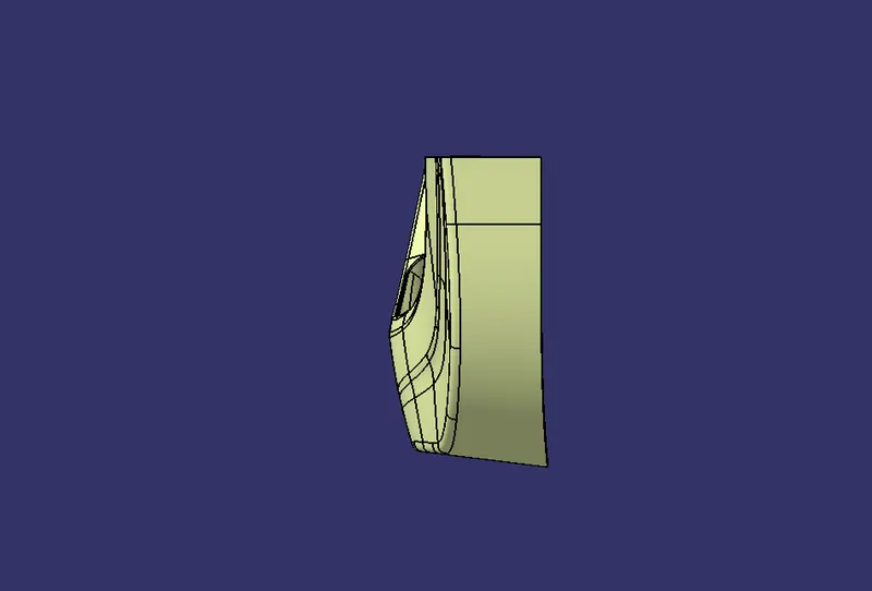
SIDE VIEW:
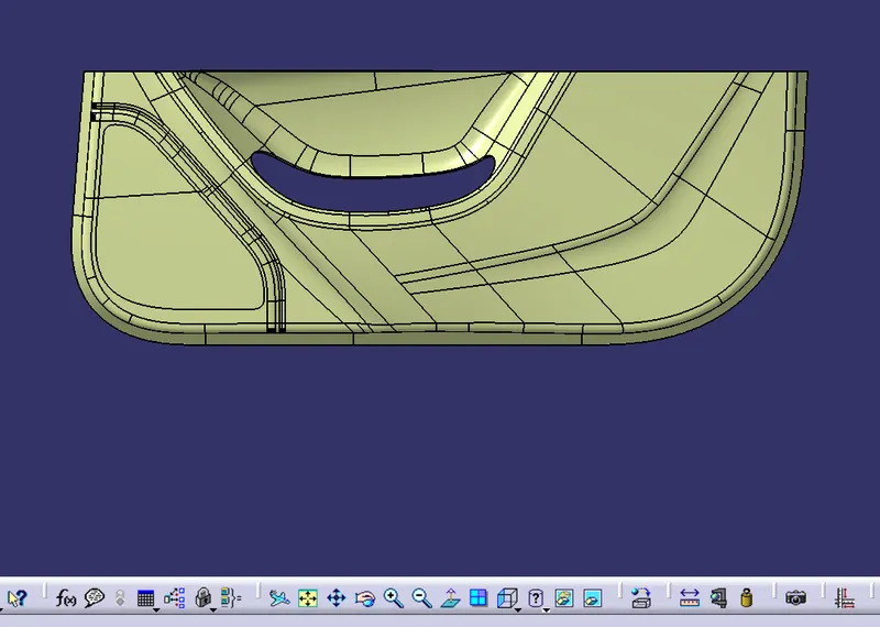
TOP VIEW:
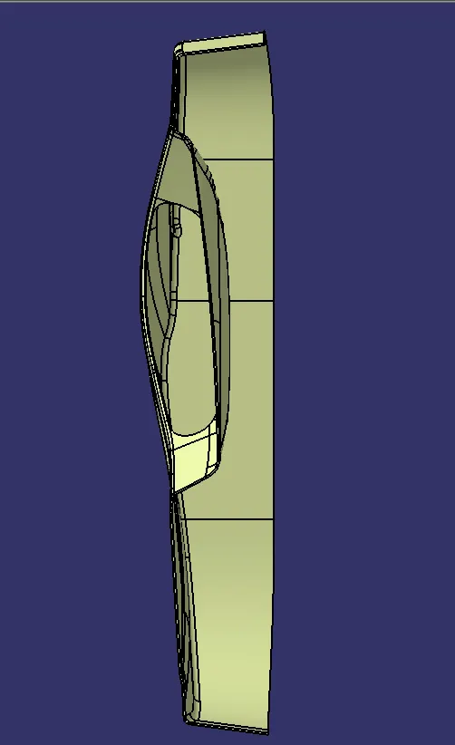
RESULT:
Thus the door drim lower was created.