Week 8 - Challenge 1 - Base Bracket Design
Objective:
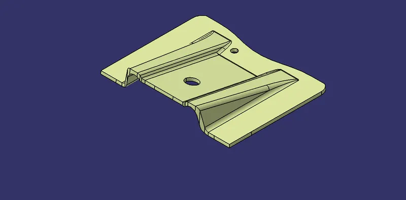
Create the Base Bracket Plastic component through the given Class-A surface. To begin with, the tooling axis for the given Class-A Surface should be created meeting the requirements of the draft angle and at the end perform the Draft analysis on the model.
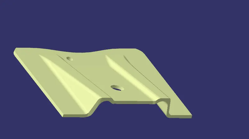
GIVEN CLASS-A SURFACE :
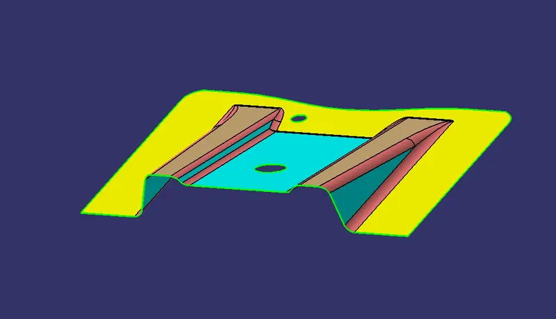
CREATING A TOOLING AXIS:
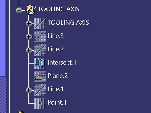
Procedure to Create Tooling axis:
- First we have to create a point in the class A surface.
- Then Dummy tooling axis created.
- Then we have to create a plane in the yz axis to create intersetion in the class A surface.
- After that we have to create lines in area where we have doubt whether the area can be drafted or not.
- After creating the line we have to create bisecting line between the lines.
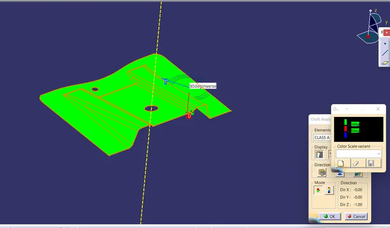
CLASS-A SURFACE DRAFT ANALYSIS :
We can clearly see that the tooling direction and the draft analysis. The Class A surface succeed in the draft analysis.
Creating Class B Surface:
After the draft analysis the class B surface can be created by the following steps in the images.
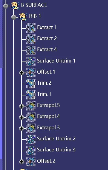
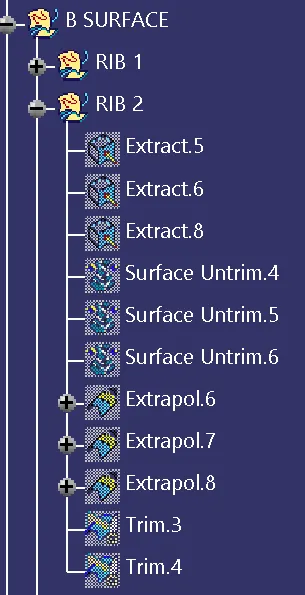
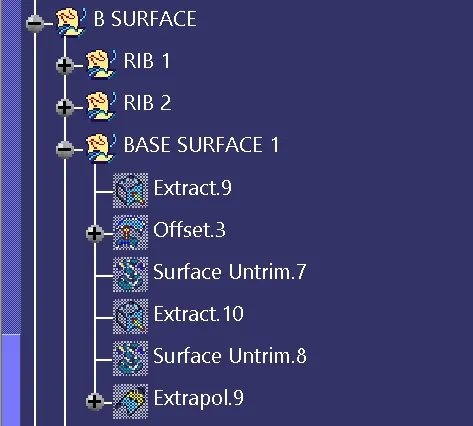
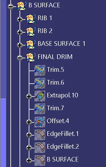
Creating Class C Surface:
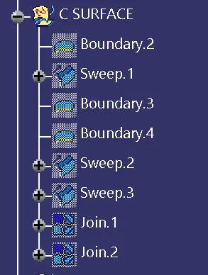
After the creation of class B surface, we have to create class C surface. That can be created by the following steps in the images.
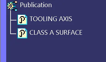
PUBLICATIONS:
FINAL CLOSESURFACE DRAFT ANALYSIS:
After the class c surface we have to create close surface in part body then we can go for draft analysis.
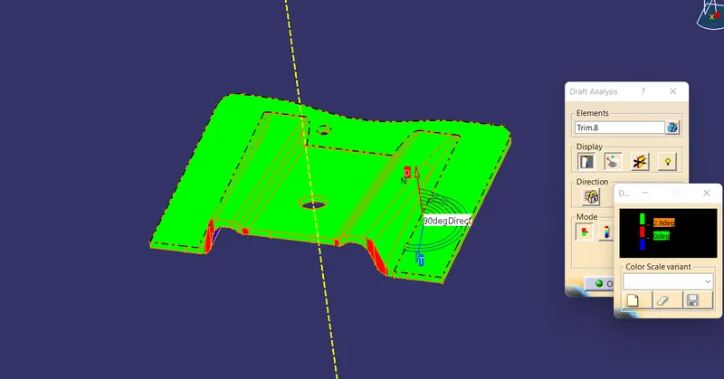
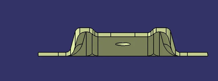
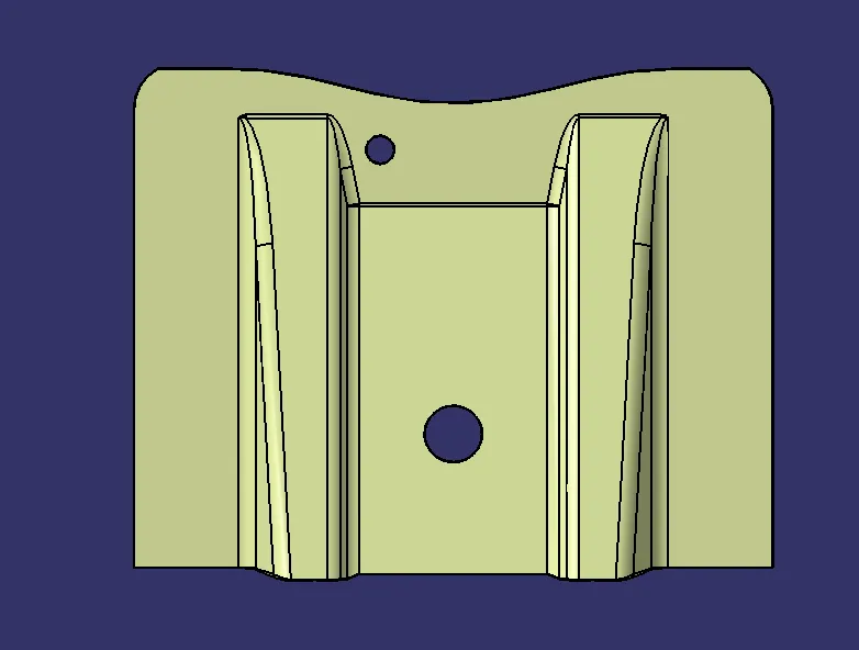
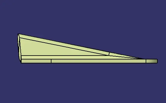
Solid model with the proper color code of the draft angle in various orientations (Isometric, Front, Side, and Top View):
Front view :
TOP VIEW :
SIDE VIEW:
ISOMETRIC VIEW: