Week 8 - Challenge 3 - Coin Holder Design
OBJECTIVE :
To make sure that the model meets the requirements of the draft angle. To create the Tooling axis using bisecting method. To perform Draft analysis on the given Class A Surface. To create the required Class.
AIM :
To create the Coin Holder Plastic component through the given Class-A surface.
OBJECTIVE :
- To make sure that the model meets the requirements of the draft angle.
- To create the Tooling axis using bisecting method.
- To perform Draft analysis on the given Class A Surface.
- To create the required Class B and Class C surfaces.
- To obtain a solid body from the surface using Close Surface feature.
PROCEDURE :
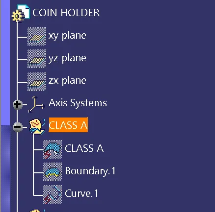
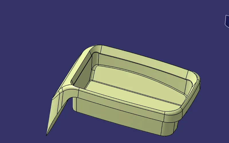
CLASS A SURFACE :
- Class A surfaces are those surfaces which are curvature continuous while providing the simplest mathematical representation needed for the desired shape and does not have any undesirable waviness.
- The Class A surface is the used to begin the design of a product.
- All the further intricacies of the component are created based on the Class A surface.
CREATE CLASS B SURFACE :
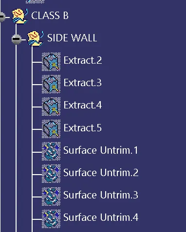
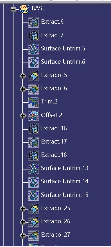
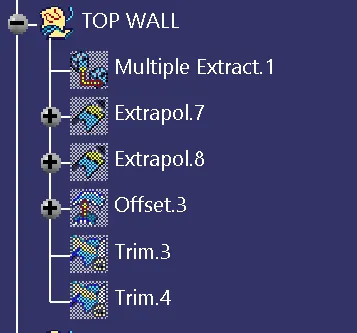
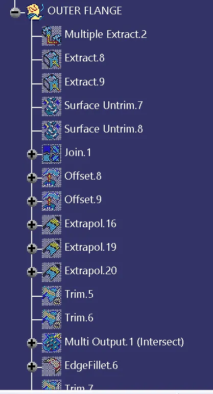
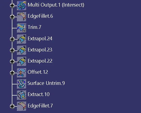
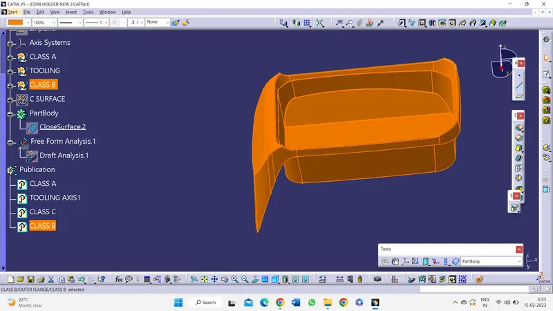
- The Class B surface was formed from four diffrent segments of surfaces.
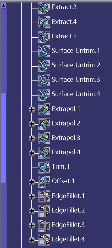
- The required surfaces were obtained from the Class A surface using Extract command.
- These surfaces were further expanded using Untrim and Extrapolate commands.
- The protuding surfaces were trimmed using the Trim command and a proper continuous surface was obtained.
- The same procedure was followed for all four segments.
- The necessary fillets were added to the Class B.
CREATE CLASS C SURFACE :
- The Class C surface is used to bind the Class A and Class B surface together inorder to form a closed surface.
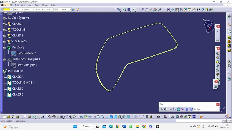
- The Outer flange of the Class B was used in the Class C creation.
- It's outer boundary was extracted.
- The Sweep surface feature was used along with With reference surface option , selction the curve and the surface which was extraced earlier.
- The angle was entered as 90 degree so that the surface protudes outside therfore intersecting the A surface.
- The Hole present in the surface was also extened outside using the above steps.
PROCEDURE :
Creating Tooling Axis
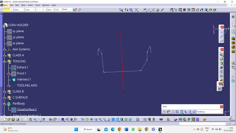
- Initially a base surface was extracted from the Class A to create a center point.
- An axis system was created upon this point.
- The Intersect feature was used to obtain a boundary of the Class A intersecting at the mid plane.
- Once the check for the discrepencies in the boundary is done, the Tooling axis was created from thr mid-point.
 .
.
Draft Analysis
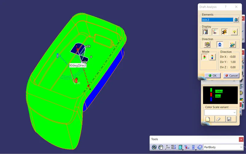
- The Drafting analysis was performed using the Feature Draft Analysis command.
- Using this command the compass was set on the main tooling axis and the Draft angle was changed to 3 degree.
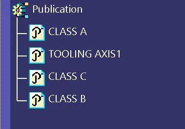
PUBLICATION
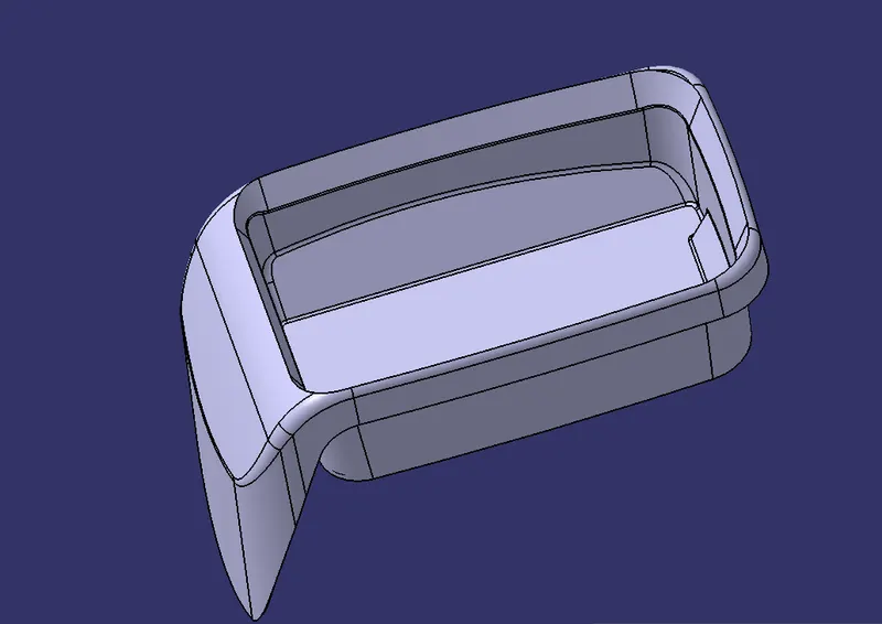
Isometric view
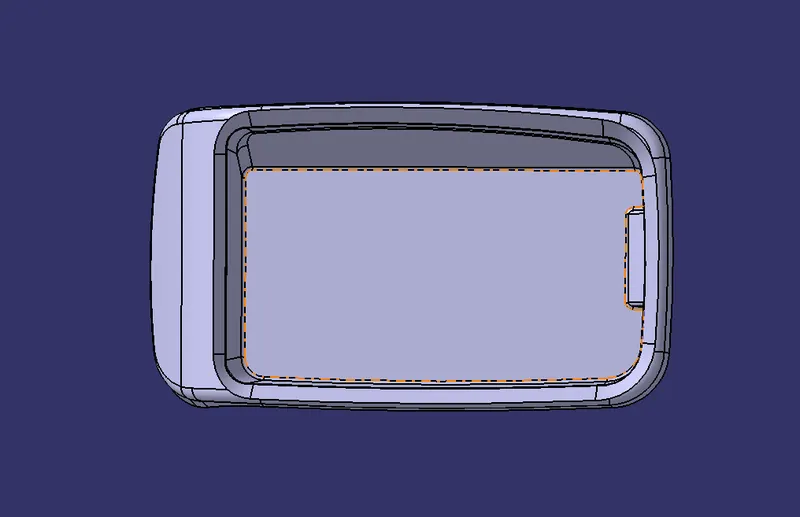
TOP VIEW
Front view
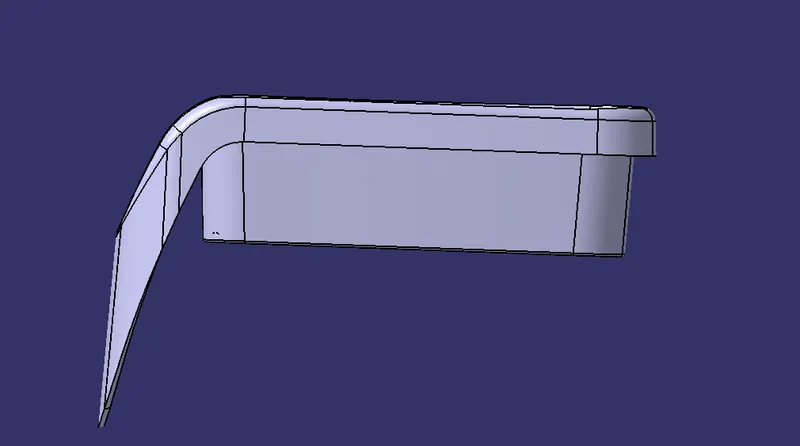
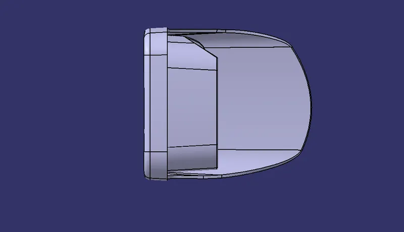
SIDE VIEW
CONCLUSION :
- The creation of Tooling axis and Draft analysis were performed.
- The solid component was created from the surface geometry.
- The necessary screenshots and files were attached.